This project is just a smart version of any keypad lock. What’s smart about it is that it can detect whether it is needed by the user or not and accordingly switches itself to take a sleep. Making a microcontroller to sleep reduces power consumption as well as increases its usage span.For this project reader should have knowledge of How to start with AVR and Interface LCD with AVR.
Many of you must be wondering that would it be secure enough to make a lock go to sleep, isn’t it. Don’t worry, when a microcontroller goes off to sleep it puts a hold on what it was doing before sleeping. In my project I have made it to sleep only when the user has finished entering the password stuff and microcontroller has done its entire job.
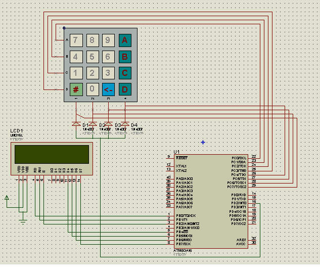
The Keypad is connected to PORTC and the LCD works on 4-bit mode with PORTB.
Requirements
Circuit Diagram
Project Source Code
###
#include<avr/io.h> #include<util/delay.h> #include<lcd.h> #include<keypad.h> void function() { LCDclr(); LCDGotoXY(0,0); LCDdisplay("ENTER PASSWORD"); LCDGotoXY(1,0); } int i=0,j=0; char k=0,arr[16]="NUL",pass[16]="1234"; void main() { DDRA=1; PORTA=0; LCDinit(); LCDcursorOFF(); while(1) { if(PINA&1) { LCDdisplay("SAFE OPEN"); LCDGotoXY(1,0); } else function(); while(i<15000) { if(!k) i++; else { if(k!='#' && k!='E') { arr[j++]=k; if(PINA&1) LCDsendChar(k); else LCDsendChar('*'); } else if(k=='E' && j!=0) { j--; LCDcursorLeft(1); LCDsendChar(' '); LCDcursorLeft(1); } else if(k!='E') { if(!strcmp(arr,"NUL")) { PORTA=0; LCDclr(); LCDdisplay("SAFE LOCKED"); _delay_ms(1000); function(); } else { arr[j]=' '; j=0; LCDclr(); if(PINA&1) { if(strlen(arr)>=4) { strcpy(pass,arr); PORTA=0;//lock the safe LCDclr(); LCDdisplay("SAFE LOCKED"); _delay_ms(1000); function(); } else { LCDdisplay("ERROR"); LCDGotoXY(1,0); LCDdisplay("WEAK PASSWORD"); _delay_ms(1000); LCDclr(); LCDdisplay("SAFE OPEN"); LCDGotoXY(1,0); } } else { if(!strcmp(arr,pass)) { LCDdisplay("SAFE OPEN"); LCDGotoXY(1,0); PORTA=1;//open the safe } else { LCDdisplay("ERROR"); LCDGotoXY(1,0); LCDdisplay("WRONG PASSWORD"); _delay_ms(1000); function(); } } strcpy(arr,"NUL"); } } i=0; } k=Read_Keypad(); } LCDclr(); DDRC=0x0f; PORTC=0x00; SREG|=(1<<7); //initializes the global interrupt i.e. sei(); DDRD&=~(1<<2); //declares INT0 as input pin PORTD|=(1<<2); //pull-up enabled GICR|=(1<<INT0); //enables INT0 GIFR|=(1<<INTF0); //enables INT0 flag for ISR recognition MCUCR|=(1<<SM0)|(1<<SM1)|(1<<SE); //sleep mode enabled MCUCR&=~(1<<SE); //sleep mode disabled } } ISR(INT0_vect) { k=Read_Keypad(); GICR&=~(1<<INT0); GIFR&=~(1<<INTF0); i=0;j=0;strcpy(arr,"NUL"); }###
Circuit Diagrams
Project Video
Filed Under: Electronic Projects
Filed Under: Electronic Projects
Questions related to this article?
👉Ask and discuss on Electro-Tech-Online.com and EDAboard.com forums.
Tell Us What You Think!!
You must be logged in to post a comment.