Engineers Garage

  • Electronic Projects & Tutorials
    • Electronic Projects
      • Arduino Projects
      • AVR
      • Raspberry pi
      • ESP8266
      • BeagleBone
      • 8051 Microcontroller
      • ARM
      • PIC Microcontroller
      • STM32
    • Tutorials
      • Audio Electronics
      • Battery Management
      • Brainwave
      • Electric Vehicles
      • EMI/EMC/RFI
      • Hardware Filters
      • IoT tutorials
      • Power Tutorials
      • Python
      • Sensors
      • USB
      • VHDL
    • Circuit Design
    • Project Videos
    • Components
  • Articles
    • Tech Articles
    • Insight
    • Invention Stories
    • How to
    • What Is
  • News
    • Electronic Product News
    • Business News
    • Company/Start-up News
    • DIY Reviews
    • Guest Post
  • Forums
    • EDABoard.com
    • Electro-Tech-Online
    • EG Forum Archive
  • DigiKey Store
    • Cables, Wires
    • Connectors, Interconnect
    • Discrete
    • Electromechanical
    • Embedded Computers
    • Enclosures, Hardware, Office
    • Integrated Circuits (ICs)
    • Isolators
    • LED/Optoelectronics
    • Passive
    • Power, Circuit Protection
    • Programmers
    • RF, Wireless
    • Semiconductors
    • Sensors, Transducers
    • Test Products
    • Tools
  • Learn
    • eBooks/Tech Tips
    • Design Guides
    • Learning Center
    • Tech Toolboxes
    • Webinars & Digital Events
  • Resources
    • Digital Issues
    • EE Training Days
    • LEAP Awards
    • Podcasts
    • Webinars / Digital Events
    • White Papers
    • Engineering Diversity & Inclusion
    • DesignFast
  • Guest Post Guidelines
  • Advertise
  • Subscribe

Miniature voltmeter with battery voltage monitor

By Fayaz Hassan October 9, 2020

Display of AVR Attiny85 based Miniature Voltmeter and Battery Level Indicator
Fig. 1: Image showing voltage reading on AVR Attiny85 based Miniature Voltmeter and Battery Voltage Monitor
Most of the time, measurement in electronic circuits is done so measuring DC voltage. Normally, we will set the multimeter to DC voltage mode and check the voltage levels at various points on the PCB… Normally, we will set the multi-meter to DC voltage mode and check the voltage levels at various points on the PCB.  Mostly, our requirement lies between 5V to 15V DC.  The circuit shown is simple, occupies less space and can directly connect to the DC voltage for measurement.  To minimize the size and power consumption, 8 pin MCU and 0.96” OLED is used in the circuit.
The Miniature Volt meter has two modes of operation.  In the first mode (12V battery mode),  It can be directly connected to 12V battery, to measure the voltage and monitor the status of the battery.  In the second mode (20VDC volt meter mode), it works as a normal DC voltmeter, which can measure from 0.0 to 20.0 VDC.
Two jumpers J1 and J2 have been provided to choose between mode1 and mode 2. Once the mode has been selected, the Attiny85 MCU continuously measure voltage through its ADC channel, at pin 7 and convert it to digital value. The value of ADC are converted to corresponding voltage value using an algorithm in the code. In the battery mode, depending on the value of ADC different status of battery (LOW, Charged, Over Charged etc) along with the current voltage level of the battery is displayed on the OLED. In the voltmeter mode, the corresponding voltage level are displayed on the OLED.
List of Components :
ATTINY85 –  1 no.
OLED 0.96” –  1 no.
LM7805 –  1 no.
1N4007 –  3 nos.
3mm LEDs –  2 nos.
100uF 50V –  1 no.
10uF 16V –  1 no.
0.1uF disc –  1 no.
5K trimpot –  2 nos.
10K 0.25W resistance –  2 nos.
4.7K 0.25W resistance –  2 nos.
8.6K 0.25W resistance –  1 no.
2.2K   0.25W resistance –  1 no.
1K   0.25W resistance –  1 no.
9V battery – 1 no.
2.54 mm Jumpers –  2 nos.
SPDT switch or sliding switch –  1 no.
Misc. = connectors,PCB,IC base, berg strip etc.
IC1 (7805) is 5V voltage regulator used for power supply of IC2 and OLED. IC2 is 8 pin MCU (ATTINY85) is heart of the circuit.  A voltage divider is used to provide input to MCU. Controller takes max 5V as input at ADC pin. Voltage divider is used to bring the voltage below 5V.
OLED (organic light emitting diode) module of 0.96” display (with 4 pin connections) is used here to make the total project compact.  Only two pins (SDA and SCL) are used for data transfer to the OLED display and two more pins for power supply.  The display has 128×64 pixel resolution.  The small text is displayed using 16X8 bit font size, where as the measured voltage is displayed as big size font using 32×24 bit font size.  
Code
Programming Guide –
In this project, ATtiny85 is programmed to display charging status of 9V or 12V battery (as per the mode selected) by measuring the terminal voltage of the battery. The MCU is coded with embedded C using AVR Studio 4.
Constants used in the code–
#define F_CPU 1000000UL :- Constant used to define clock frequency of the MCU
#define BLINKER 0b00000001  :- Constant used to blink LED as indication that MCU is working properly.
#define BATT12V 0B00000010 :- Constant used to set 12V battery mode.
Variables used in the code–
A :– Variable used to store analog reading from 10-bit ADC Channel
V :– Variable used to convert ADC reading to voltage and indicate battery status
Prev_mode :– Variable used to indicate previous battery mode (12V or 20V battery mode)
current_mode :- Variable used to indicate current battery mode (12V or 20V battery mode)
dispstr[6]={‘0′,’0′,’.’,’0′,’/’,0} :- Array used to define the format of OLED
Header files and libraries used in the code–
#include <avr/io.h> :- Standard AVR header for input output
#include <util/delay.h> :- Standard AVR header to provide time delays
#include <avr/pgmspace.h> Standard AVR header including program space utilities
#include “OLED_LIB.C” :- General purpose library containing functions for working with 0.96” OLED. This library can be used with any AVR microcontroller. Note that OLED_LIB defines pin 2 as SDA and pin 3 as SCL of ATtiny85.
#include “FONT_BASIC_16x8.H” :- This header file contains 16×8 pixel (small) size Alphabet, numbers and symbols.
#include OLED_NUMS_32x24.H :- This header file contains 32×24 pixel (big) size only numbers to display voltage value.
Functions used in the code–
ADC_init() :- function used to initialize ADC channel.
readADC() :- function used to read analog voltage from ADC Channel 1
OLED_init() :- function used to start OLED display
OLED_floodfill() :- function used to display bright light by passing parameter 0xFF or clear OLED by passing parameter 0x00.
Algorithm –
1)    When the Voltmeter circuit is powered on, first of all, the OLED is initialised and checked by displaying a bright light. Then, the OLED display is cleared and a welcome message – “Welcome to Miniature Voltmeter” is flashed on it. The MCU starts blinking an LED to indicate that it is working properly. The MCU checks the status of battery mode (12V or 20V mode) by checking the digital input at pin 6 of Attiny85. Now the controller is ready to take voltage readings.

DDRB = BLINKER;

OLED_init();        // start displaying OLED

_delay_ms ( 10 );

OLED_floodfill(0xFF);   // display OLED with bright light as self test

_delay_ms ( 500 );

ADC_init ( );                  // initialize ADC system

OLED_floodfill(0x00);  // blank display of OLED

_delay_ms ( 500 );

OLED_show_str_16x8 ( ” WELCOME TO “,6,0);   // a welcome message

OLED_show_str_16x8 ( ” MINIATURE “,11,3);          // is displayed on OLED

OLED_show_str_16x8 ( ” VOLT METER “,6,6);          // as self test of text display on OLED

_delay_ms ( 1000 );

OLED_floodfill(0x00);  // blank display of OLED

_delay_ms ( 300 );

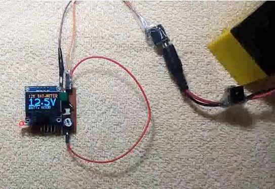
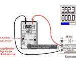
2)    The user can take voltage reading of a standard (or known) voltage source and adjust the respective pot (as per the current battery mode) to calibrate the voltmeter. In this circuit, the voltmeter is calibrated using a standard 12V voltage source where ADC reading is adjusted to 900 (for 12V input) in 12V battery mode and 750 (for 12V input) in 20V battery mode. After calibration, the miniature voltmeter is expected to give exactly accurate voltage readings.

3)    The MCU senses the voltage from 12V or 20V battery at pin 7 (ADC Channel 1) using readADC() function and store that read value to variable A. The ATtiny85 has 10-bit ADC channel, so the ADC reading (stored in variable A) can range from 0 to 1023. For comparison of voltage to indicate battery status, ADC reading of 750 is equivalent to 12 V in case of 20V battery mode and ADC reading of 900 is equivalent to 12V in case of 12 V battery mode. 
4)    The value stored in A is converted to voltage and stored in variable V by assuming that value of A being 750 ( in case of 20V battery mode) or 900 (in case of 12V battery mode) is equivalent to real voltage of 12V. Note that conditions for indicating battery status are defined in the code accordingly. The above assumption is derived from calibration of the miniature voltmeter. In 20V battery mode, on using known voltage of 12V, ADC reading is calibrated to 750 using the pot. Similarly, in 12V battery mode, on using known voltage of 12V, ADC reading is calibrated to 900 using the respective pot. Note that the conversion of ADC reading to voltage is here dependant on calibration. The standard formula for single ended conversion (Vin = ADC*Vref/1024) is not used in the code considering the fact that resting voltage from different batteries can be different and may not fit to a standard calibration equation.  
PORTB ^= BLINKER;                         // toggle blinker to indicate MCU is working
A = readAdc ( 1 );                               // read ADC value from channel no 1
curr_mode = (PINB & BATT12V);  // check the mode of operation by usage of jumper J2
// for 12V battery mode or 20VDC voltmeter
if ( prev_mode != curr_mode )
{
OLED_floodfill(0x00);
_delay_ms ( 50 );
}
if ( curr_mode>0 )
V = A/6;
else
V = A/5;
5)     The value of V is compared in else-if statements to indicate charging status of attached battery.
if ( curr_mode>0 )        // in case of 12V battery mode, appropriate status is diplayed on OLED
{
OLED_show_str_16x8 ( "12V BAT.METER",0, 0);
if ( V>150 )
OLED_show_str_16x8 ( "NOT 12V BAT  " , 0 ,6);
else if ( V>135 )
OLED_show_str_16x8 ( "OVER CHARG   " , 0 ,6);
else if ( V>120 )
OLED_show_str_16x8 ( "BATT. GOOD   " , 0 ,6);
else if ( V>100 )
OLED_show_str_16x8 ( "BATT. LOW    " , 0 ,6);
else if ( V>90 )
OLED_show_str_16x8 ( "BATT. WEAK   " , 0 ,6);
else if ( V>60 )
OLED_show_str_16x8 ( "BATT. DEAD   " , 0 ,6);
else //if ( V<30 )
OLED_show_str_16x8 ( "BATT.ABSENT  " , 0 ,6);
}
6)    The value of V is formatted to decimal notation and read voltage is shown on the OLED display.  
dispstr[0]=V/100+'0';
V=V%100;
dispstr[1]=V/10+'0';
dispstr[2]='.';
dispstr[3]=V%10+'0';
dispstr[4]='/';
dispstr[5]=0;
7)    The ADC reading stored in A is compared with 1000 to check if the voltage exceeds the designated range.
if ( A>1000 )      // in case the ADC read value is out of range then display as OVERFLOW
{
OLED_show_str_16x8 ( " OVERFLOW  " , 0 ,0);
_delay_ms ( 150 );
OLED_show_str_16x8 ( "" , 0 ,0);
_delay_ms ( 100 );
}
Working: 
Initial Setup:  
After assembling the circuit on a PCB, connect power supply by turning SW1 towards 9V battery.  Then load/burn the miniVoltMeter.hex file to the MCU (ATTINY85) using any AVR programmer. 
Initially, OLED displays all pixels (128×64) in ON mode, makes the display bright for a while.  Then displays a welcome message as WELCOME TO MINIATURE VOLT METER.  Then displays the random voltage, which is yet to be calibrated.
Now, set the board for 12V BATTERY MODE, by connecting Jumper J1 and disconnecting jumper J2. Then, connect a known voltage source of about 12VDC or a 12V battery to the signal terminals (or connect a multi-meter parallel to terminals to know exact input voltage).  Now, set the trim-pot VR1, to show the display to the correct voltage on the OLED.
Now, set the board for VOLT METER MODE, by disconnecting jumper J1 and connecting jumper J2.  Then, with the same voltage source as input signal set the trim-pot VR2, to show the display to the correct voltage on the OLED.
Now, calibration is complete and the circuit is ready for use.  Disconnect the signal input and set the board for one of the modes as per the requirement.
There are two modes of operation. 12 V and 20V.
For 12V battery mode, connect jumper J1 and disconnect jumper J2.  The voltage is read by ADC channel of MCU and displays the battery voltage on OLED using big font.  The top-line of OLED shows as 12V BAT. METER and bottom-line shows the status of the battery as BATT.ABSENT / BATT.DEAD / BATT.WEAK / BATT.GOOD / OVER CHRG. etc.
For 20VDC volt-meter mode, disconnect jumper J1 and connect jumper J2.  the input signal voltage is read by ADC channel of the MCU and displays on OLED with big font at center. Here, the top-line of OLED shows VOLT METER and bottom-line shows 20 DC VOLTS.  
In both the modes, if the input voltage exceeds the ADC input voltage value (about 5VDC), the top-line blinks with the message OVERFLOW.  In case, to read weak signal or voltages less than 8VDC, SW1 must be turned towards 9V battery connection. The miniature Volt Meter circuit can be used as quick DC volt meter for desktop purposes, voltage and status monitor for Battery chargers, Battery banks etc. 


You may also like:

  • batteries
    Introduction to batteries and their types
  • battery types
    What are the different battery types for specific applications?
  • battery configurations
    Battery configurations (series and parallel) and their protections

  • Understanding battery management systems

  • What is a loop calibrator? 
  • ATtiny85
    ATtiny85 microcontroller tutorials, Part 1: Introduction

Project Source Code


/*
Filename : miniVoltMeter.C
author   : Fayaz Hassan
Date     : 15-02-2018
MCU      : ATtiny85 (A)
Display  : OLED (I2C)
*/
#define F_CPU 1000000UL
#include 
#include 
#include 
#include "OLED_LIB.C"
#define BLINKER 0b00000001  
#define BATT12V 0B00000010  

//========================================================================================

void ADC_init ( )
{

    ADCSRA |= ( (1 << ADPS2) | (1 << ADPS1) | (1 << ADPS0) | (1 << ADEN) ); 

}

//========================================================================================

int readAdc ( int channelno )

{

    ADMUX = (channelno%4);
    ADCSRA |= (1 << ADSC);
    while (ADCSRA & (1 << ADSC));
    return ADC;

}
//========================================================================================
int main ( )

{
    int V=0;
    int A=0;
    int prev_mode = -1;
    int curr_mode = 0;
    char dispstr[6]={'0','0','.','0','/',0};
    _delay_ms ( 500 );
    DDRB = BLINKER;
    OLED_init();
    _delay_ms ( 10 );
    OLED_floodfill(0xFF);
    _delay_ms ( 500 );
    ADC_init ( );
    OLED_floodfill(0x00);
    _delay_ms ( 500 );
    OLED_show_str_16x8 ( " WELCOME TO ",6,0);
    OLED_show_str_16x8 ( " MINIATURE ",11,3); 
    OLED_show_str_16x8 ( " VOLT METER ",6,6); 
    _delay_ms ( 1000 );
    OLED_floodfill(0x00);
    _delay_ms ( 300 );
    readAdc ( 1 );
    readAdc ( 1 );
    while ( 1 )

{

    PORTB ^= BLINKER;
    A = readAdc ( 1 );
    curr_mode = (PINB & BATT12V);
    if ( prev_mode != curr_mode )

{

    OLED_floodfill(0x00);
    _delay_ms ( 50 );

}

    if ( curr_mode>0 )
    V = A/6;
    else
    V = A/5;
    if ( curr_mode>0 )
{

    OLED_show_str_16x8 ( "12V BAT.METER",0, 0);
    if ( V>150 )
    OLED_show_str_16x8 ( "NOT 12V BAT  " , 0 ,6);
    else if ( V>135 )
    OLED_show_str_16x8 ( "OVER CHARG   " , 0 ,6);
    else if ( V>120 )
    OLED_show_str_16x8 ( "BATT. GOOD   " , 0 ,6);
    else if ( V>100 )
    OLED_show_str_16x8 ( "BATT. LOW    " , 0 ,6);
    else if ( V>90 )
    OLED_show_str_16x8 ( "BATT. WEAK   " , 0 ,6);
    else if ( V>60 )
    LED_show_str_16x8 ( "BATT. DEAD   " , 0 ,6);
    else //if ( V<30 )
    OLED_show_str_16x8 ( "BATT.ABSENT  " , 0 ,6);
}

    else

{

    OLED_show_str_16x8 ( " VOLT METER " ,4, 0);
    OLED_show_str_16x8 ( "0-20 DC VOLTS" ,0 ,6);
}

    dispstr[0]=V/100+'0';
    V=V%100;
    dispstr[1]=V/10+'0';
    dispstr[2]='.';
    dispstr[3]=V%10+'0';
    dispstr[4]='/'; 
    dispstr[5]=0;
    if ( dispstr[0]=='0' )
    dispstr[0] = ':';
    OLED_show_str_32x24 ( dispstr , 5, 0,2);
    if ( A>1000 )

{

    OLED_show_str_16x8 ( " OVERFLOW  " , 0 ,0);
    _delay_ms ( 150 );
    OLED_show_str_16x8 ( "           " , 0 ,0);
    _delay_ms ( 100 );

}

prev_mode = curr_mode;

} 

return 0;

}
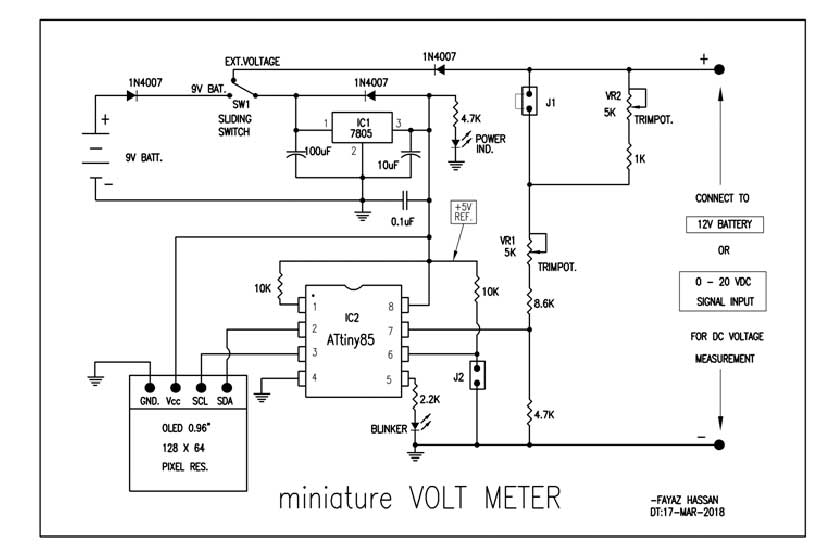


Circuit Diagrams

Circuit-Diagram-MiniatureVOLT-METER-cum-Battery-Voltage-Monitor

Project Video


Filed Under: Electronic Projects
Tagged With: ATtiny85, batteries, voltmeter
 

Next Article

← Previous Article
Next Article →

Questions related to this article?
👉Ask and discuss on EDAboard.com and Electro-Tech-Online.com forums.


Tell Us What You Think!! Cancel reply

You must be logged in to post a comment.

EE TECH TOOLBOX

“ee
Tech Toolbox: Internet of Things
Explore practical strategies for minimizing attack surfaces, managing memory efficiently, and securing firmware. Download now to ensure your IoT implementations remain secure, efficient, and future-ready.

EE Learning Center

EE Learning Center
“engineers
EXPAND YOUR KNOWLEDGE AND STAY CONNECTED
Get the latest info on technologies, tools and strategies for EE professionals.

HAVE A QUESTION?

Have a technical question about an article or other engineering questions? Check out our engineering forums EDABoard.com and Electro-Tech-Online.com where you can get those questions asked and answered by your peers!


RSS EDABOARD.com Discussions

  • Voltage mode pushpull is a nonsense SMPS?
  • Input impedance matching network
  • High Side current sensing
  • The comparison of different Tcl script checkers
  • Reducing "shoot-through" in offline Full Bridge SMPS?

RSS Electro-Tech-Online.com Discussions

  • Is AI making embedded software developers more productive?
  • Back to the old BASIC days
  • Parts required for a personal project
  • PIC KIT 3 not able to program dsPIC
  • Failure of polypropylene motor-run capacitors

Featured – RPi Python Programming (27 Part)

  • RPi Python Programming 21: The SIM900A AT commands
  • RPi Python Programming 22: Calls & SMS using a SIM900A GSM-GPRS modem
  • RPi Python Programming 23: Interfacing a NEO-6MV2 GPS module with Raspberry Pi
  • RPi Python Programming 24: I2C explained
  • RPi Python Programming 25 – Synchronous serial communication in Raspberry Pi using I2C protocol
  • RPi Python Programming 26 – Interfacing ADXL345 accelerometer sensor with Raspberry Pi

Recent Articles

  • What is AWS IoT Core and when should you use it?
  • AC-DC power supply extends voltage range to 800 V DC
  • Infineon’s inductive sensor integrates coil system driver, signal conditioning circuits and DSP
  • Arm Cortex-M23 MCU delivers 87.5 µA/MHz active mode
  • STMicroelectronics releases automotive amplifiers with in-play open-load detection

EE ENGINEERING TRAINING DAYS

engineering

Submit a Guest Post

submit a guest post
Engineers Garage
  • Analog IC TIps
  • Connector Tips
  • Battery Power Tips
  • DesignFast
  • EDABoard Forums
  • EE World Online
  • Electro-Tech-Online Forums
  • EV Engineering
  • Microcontroller Tips
  • Power Electronic Tips
  • Sensor Tips
  • Test and Measurement Tips
  • 5G Technology World
  • Subscribe to our newsletter
  • About Us
  • Contact Us
  • Advertise

Copyright © 2025 WTWH Media LLC. All Rights Reserved. The material on this site may not be reproduced, distributed, transmitted, cached or otherwise used, except with the prior written permission of WTWH Media
Privacy Policy

Search Engineers Garage

  • Electronic Projects & Tutorials
    • Electronic Projects
      • Arduino Projects
      • AVR
      • Raspberry pi
      • ESP8266
      • BeagleBone
      • 8051 Microcontroller
      • ARM
      • PIC Microcontroller
      • STM32
    • Tutorials
      • Audio Electronics
      • Battery Management
      • Brainwave
      • Electric Vehicles
      • EMI/EMC/RFI
      • Hardware Filters
      • IoT tutorials
      • Power Tutorials
      • Python
      • Sensors
      • USB
      • VHDL
    • Circuit Design
    • Project Videos
    • Components
  • Articles
    • Tech Articles
    • Insight
    • Invention Stories
    • How to
    • What Is
  • News
    • Electronic Product News
    • Business News
    • Company/Start-up News
    • DIY Reviews
    • Guest Post
  • Forums
    • EDABoard.com
    • Electro-Tech-Online
    • EG Forum Archive
  • DigiKey Store
    • Cables, Wires
    • Connectors, Interconnect
    • Discrete
    • Electromechanical
    • Embedded Computers
    • Enclosures, Hardware, Office
    • Integrated Circuits (ICs)
    • Isolators
    • LED/Optoelectronics
    • Passive
    • Power, Circuit Protection
    • Programmers
    • RF, Wireless
    • Semiconductors
    • Sensors, Transducers
    • Test Products
    • Tools
  • Learn
    • eBooks/Tech Tips
    • Design Guides
    • Learning Center
    • Tech Toolboxes
    • Webinars & Digital Events
  • Resources
    • Digital Issues
    • EE Training Days
    • LEAP Awards
    • Podcasts
    • Webinars / Digital Events
    • White Papers
    • Engineering Diversity & Inclusion
    • DesignFast
  • Guest Post Guidelines
  • Advertise
  • Subscribe