A simple circuit of variable power supply and charger is described here. It is useful when the main power supply is available or when there is no power supply.This circuit can be used for testing electronic projects at your work bench. It can be used to charge your mobile battery. It can be used as an emergency light. In this circuit you can take outputs by flipping the different switches according to your requirement. Engage switch S3 if you want a variable power supply as output. For variable power supply, we have used variable voltage regulator LM317whichis a 3 terminal adjustable positive voltage regulator. It will provide an output voltage in the range of 1.2V to 37V. For obtaining different voltages, adjust the variable resistor to see the output on the multimeter and set the required voltage. Range of power supply varies from 1.5V-12V.
Smart Capacitor power supply
This capacitor power supply can deliver 12 volt DC and 100 mA current to power low current devices. It is provided with surge protection and is totally isolated from mains supply using two capacitors in the phase and neutral lines. So the connected device is safe even if the phase and neutral lines changes. Transformer…
Smartphone operated shopping cart controlled using bluetooth

Shopping carts are handy, but all these carts require a push or pull to move around. How about we create a battery-operated cart that doesn’t require human efforts? In this project, we will design a mini motorized battery-powered shopping cart using four DC motors attached to four wheels, which can be controlled using a Bluetooth…
FM Transmitter Bug: Learn how to Make one
The proposed simple electronic spy Bug circuit is basically a high gain amplifier using the IC 741 as the heart of the circuit and also a couple of high gain output transistors. The IC 741 if configured as a non-inverting amplifier which performs the function of a pre-amplifier stage. The gain of this IC 741 preamplifier stage may be varied as desired, using the pot across its input and output pin outs. The gain setting is used to set the sensitivity of the amplifier and is set to maximum so that even low volume speech conversation may be picked through it. The mic at the input transforms sound vibrations into minute electrical pulses, which is further amplified by the IC 741 to suitable levels before applying it to the output amplifier stage consisting of a standard DARLINGTON stage. This Darlington stage is made using a couple of high gain transistors bc107A’s.
Exhaust Fan Circuit Diagram

Many of us have modular kitchen which have chimney to extract smoke out so that smell of smoke will not fill in kitchen and avoids the harmful effects of smoke on furniture and kitchen utensils. But sometimes it happens we forget to switch on the chimney which results in smoke in kitchen and sometimes we forget to off the chimney leading to the wastage of electricity and money. So to solve this problem we have described a circuit which will switch on the fan automatically when smoke reaches to point and off the fan automatically.You can also use this circuit while soldering because as we know solder fumes are not good for health so it will on the fan to extract the smoke present in room leaving smoke free area.
Circuit Design: Pulse Amplitude Demodulation
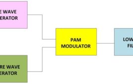
The simple pulse modulation technique called Pulse Amplitude Modulation (PAM) proved to be more power efficient than the PWM and consumes constant power for individual pulses like PPM. In PAM the amplitude of the individual pulses are varied according to the amplitude of the modulating signals. The PAM modulator and demodulator circuits simple compared…
DIY – Homemade Melody Door Bell

In most of the homes the door bells are conventional ding-dong type. Most of us don’t like its sound. Due to mechanical moving parts with spring mechanism its long term durability is questionable. I had also one such door bell in my home. After a period of time its performance deteriorates and one time it becomes completely intolerable because of its noisy irritating sound.The new types of door bells available in market are bird sound door bell. They are costly and even I didn’t like it because of its high frequency and high volume sound output.
Smartphone-operated omnidirectional robot
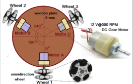
There are many different types of robot projects that you might be aware of including the following: Remote-controlled robot (car type 3/4-wheeler) Joystick controlled robot Gesture controlled robot Smartphone (Bluetooth) controlled robot Obstacle avoidance robot Object follower robot Object finder robot Robotic Arm Pick and place robot And many more This article also describes a…
Insight – How Head Phone TRS Connector or Jack works
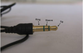
Ever wondered how are wires connected to a connector. How different number of wires are connected to segments of the connector? A connector aka jack for the earphone, headphone, microphone, like any other gadgets has an equally interesting chapter in the book s of engineering. It is among the cheapest part but not the technically inferior. It deserves its attention from the engineers for its design and quality.The connector plays an important part of tranferring signals from the device like mobile, laptops, music players etc to the earphone and the microphone and vice versa. Even a small problem may lead to an unplesant experience with the device. The connector has three contacts/segments/parts called the TIP, RING, and the Sleeve. Therefore it is also called the TRS connector.
Memory Devices for Digital Systems – DE Part 21

In the previous tutorials, it was learnt that sequential circuits require memory elements to retain previous states of a digital system. The flip-flops and registers were then introduced as building blocks of memory in a sequential circuit. The registers are enough to store runtime data in small microcontrollers and ASICs. The complex computing systems require digital memory to not only store runtime information (as stored by registers in a microcontroller) but to store programs and data permanently within the digital system. So, they require dedicated memory either internal or external.
CD4001 IC -based Lighting System
CD 4001 is a quad, 2 input NOR gate IC made by Fairchild Semiconductors. It is a monolithic CMOS transistor based IC having efficient source and sink [[wysiwyg_imageupload::]]capabilities. Circuits that use this IC can be easily operated using battery as CD4001 is a low power consumption IC. A 14 pin DIP package, this IC can work at temperatures upto 1250. The circuit in this project is built around a commonly used CD4001 IC and few more discrete components. The circuit described can be used to decorate your Christmas tree with colorful lights. The blinking of LED’s will create a festive appearance which will enhance the Christmas mood.
Toggle flip flop using CD4013
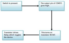
The circuit uses the CMOS dual D type flip flop CD4013 which contains two positive-edge triggered flip flop to toggle a load connected through a relay. Now [[wysiwyg_imageupload::]]with the help of a switch you can on the device once pressing it and off the device again using the same switch. In CD4013 each module is further equipped with a group of pin outs assigned as data, set, reset, clock input and a couple complementary output Q and Q(not) . As we know it has couple of output that change or toggle state as response to trigger applied to input terminals. In this circuit, one is wired in toggle mode while other is not used. Using this circuit we can easily control AC and DC appliances remotely through inexpensive low voltage cable and a standard push to on switch. This circuit can easily support a cable length of 25 meters.
Web Browsers : What is Web Browser

By the time you are reading this article, certainly you are already using a web browser which is presenting this article content in a rich text/graphical format on your computer screen. A web browser or frequently called as browser is an application software that is installed on a computer to provide access to the World Wide Web. I t fetches the web pages from the server along with the necessary files like, images, flashes, videos etc, interprets them and then displays it on the screen.
Circuit Design: Reproduce Sound Signals Captured through a Microphone

This article discusses about a simple circuit that can reproduce the sound signals captured through a microphone on a loudspeaker. The microphone is a device which is used to capture sound signals and forms an essential part of most of the electronic gadgets. The microphone converts the sound signals in the environment to their corresponding electrical signals.
Circuit Design: Bass Separator

This article discusses how to design a simplest active bass separator circuit with design details. This is basically a low pass circuit which is used to separate out low frequency sounds from audio signals at audio play back devices. A simple loudspeaker is not capable of reproducing all the frequencies of the audible range. Different kinds of loudspeaker are available which can reproduce the sound at certain range of frequencies. The bass separator circuit alone is realized with the help of commonly available op-amp ICs. For demonstrating the working a bass beat is played in a mobile phone which is captured, amplified and mixed with a high frequency musical signal and is then again separated out using the bass separator circuit and reproduced in a loudspeaker. Read more to find out how the circuit is assembled and how it is tested and used.
Circuit Design: Automatic Gain Control

The amplifiers are devices which produces an output signal which is several times higher in amplitude than the input signals. The ratio of the amplitude of the output signal from an amplifier circuit to the amplitude of the input signal is called Gain. The amplifier circuits are normally designed for a fixed amount of gain. There are amplifiers with very low gain, like the amplifiers at the loudspeaker side of an audio device and also there are amplifiers with very high gain, like the amplifiers in the radio receivers or amplifiers at the microphone side of an audio device. The Automatic Gain Control (AGC) amplifiers are another category of amplifiers which can vary its gain according to the input signal level. They provide enough amplification for the weak signals and prevent strong signals from getting over amplified.
Electronic Circuit Designing: Modular Approach (Part 1)

A person’s inquisitiveness and curiosity can do wonders. It can open a realm of ideas and imaginations never thought before and create something worthwhile. When I was a child I used to read lot of electronic articles and magazines regularly. I’ve seen a lot of interesting circuits and tried as many of them as possible at that time. Whenever a new circuit catches my attention I can’t resist myself trying it out.
Electronic Circuit Designing: Modular Approach (Part 2)

Up to this point, we were developing the basic functions into specific functional blocks according to their requirements. Let’s take a look at what all functional blocks we have, it will give you an idea how far we advanced in the designing processEach of the blocks shown above can perform their own specified functions only. The entire blocks should perform together to give us a collective output. It will happen only when we connect the blocks together in the proper way. Next we are going to discuss how to connect these blocks together so that we have a complete block diagram for the device. From the entire discussion so far you might already have a picture about the way of connecting these blocks together. The IR light from the TV remote triggers the working of the device and who receives the IR light pulses from the TV remote, the IR photodiode.
Electronic Circuit Designing: Functional Block Designing (Part 3)

Step: 5) Design circuit for each functional block In this step we will be designing the circuit for individual blocks. The circuits required are simple and very basic circuit known to all; hence it won’t be such a big task. We are not designing anything new, but modifying the well-known basic circuits to suit our…
Electronic Circuit Designing: Multitasking With Circuits (Part 4)

Step: 8) Find reusable modules from the circuit diagram Whenever we do hardware designing, the first rule is to make it in modules that can be reusable. The modules that we make for this particular project may come useful in another project and hence reduce the development time for that project. Even if a…