Engineers Garage

  • Electronic Projects & Tutorials
    • Electronic Projects
      • Arduino Projects
      • AVR
      • Raspberry pi
      • ESP8266
      • BeagleBone
      • 8051 Microcontroller
      • ARM
      • PIC Microcontroller
      • STM32
    • Tutorials
      • Audio Electronics
      • Battery Management
      • Brainwave
      • Electric Vehicles
      • EMI/EMC/RFI
      • Hardware Filters
      • IoT tutorials
      • Power Tutorials
      • Python
      • Sensors
      • USB
      • VHDL
    • Circuit Design
    • Project Videos
    • Components
  • Articles
    • Tech Articles
    • Insight
    • Invention Stories
    • How to
    • What Is
  • News
    • Electronic Product News
    • Business News
    • Company/Start-up News
    • DIY Reviews
    • Guest Post
  • Forums
    • EDABoard.com
    • Electro-Tech-Online
    • EG Forum Archive
  • DigiKey Store
    • Cables, Wires
    • Connectors, Interconnect
    • Discrete
    • Electromechanical
    • Embedded Computers
    • Enclosures, Hardware, Office
    • Integrated Circuits (ICs)
    • Isolators
    • LED/Optoelectronics
    • Passive
    • Power, Circuit Protection
    • Programmers
    • RF, Wireless
    • Semiconductors
    • Sensors, Transducers
    • Test Products
    • Tools
  • Learn
    • eBooks/Tech Tips
    • Design Guides
    • Learning Center
    • Tech Toolboxes
    • Webinars & Digital Events
  • Resources
    • Digital Issues
    • EE Training Days
    • LEAP Awards
    • Podcasts
    • Webinars / Digital Events
    • White Papers
    • Engineering Diversity & Inclusion
    • DesignFast
  • Guest Post Guidelines
  • Advertise
  • Subscribe

Interfacing 7 segment display with stm32f103 microcontroller

By EG Projects September 4, 2021

This tutorial is about interfacing 7 segment led display with stm32 microcontroller using keil arm mdk 5 with stm32 HAL libraries for code compilation. Stm32cubemx is used to initialize the stm32f103c8t6 microcontroller peripherals/variables pins, operating frequency, oscillator selection etc. Stm32cubemx initialized settings are then imported to keil mdk arm 5 project. Stm32cubemx automatically generates code for the ide we want to work in and in this project i am going to use keil arm mdk 5 ide. If you are new and don’t know about the stm32cubemx and keil uvision arm ide. I suggest you to learn more about the Stm32cubemx and keil uvision mdk arm ide used together stm32 HAL libraries for stm32 microcontroller code generation. Just click the below button to take the tutorial  

Getting started stm32cubemx and keil mdk arm ide

Coming to the main project. In this tutorial i am going to interface a seven segment display with stm32f103 microcontroller. I will print numbers from 0 to 9 and characters from A to F on a single seven segment display. Seven segment display is composed of led’s arranged in a matrix form. Switching led’s on and off in a dedicated pattern prints the desired number or character on a 7 segment display. There are two types of seven segment displays common anode and common cathode. Common anode seven segment display has all led’s anode pin’s connected to a single point. Where as in common cathode all the cathode pin’s are connected to single point. To learn more about the difference between types, sizes and special 7 segment displays take the below tutorial. Click the below button to take the tutorial.

Difference between 7 segment sizes and types.

I am going to use common anode 7 segment display in this project. Stm32 microcontrollers are not easy to use. They do not come in DIP package. So its not possible to make a diy project with them on a bread board. We need to design a special pcb for working with stm32 microcontrollers which is still a time consuming work. Luckily their are number of pre assembled stm32 getting started boards available in market. They are not only cheap but are also easy to work with. I am also going to use a pre assembled stm32 board housing a stm32f103c8t6 microcontroller on it.      
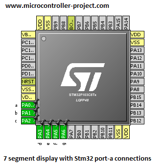
First an initialization is done in the stm32cubemx for stm32f103c8t6 microcontroller. 7 stm32 microcontoller pins are initialed as output which are going to be interfaced with the seven segment display. Pins are named same as seven segment display pins. Port-A pins of stm32 microcontroller are used in the project. Port-A of stm32 microcontroller is a 16-bit wide port. I am going to use its first 7 pins from 0 to 6 in the project. Stm32cubemx configuration for declaring pins as output is shown at the right side.   

Stm32cubemx 7 segment settings for stm32f103 microcontroller

Stm32cubemx 7 segment settings for stm32f103 microcontroller

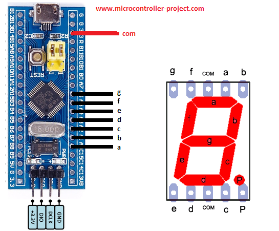
Project circuit diagram

The board which i am using in the project is in the below circuit diagram. Though in the board not all the GPIO pins of stm32f103 microcontroller are exposed but still it has pretty fair amount of GPIO pins to work with. Port-A of stm32f103 has 16 GPIO pins but only 12 are exposed on the board. Luckily port-a pins from 0 to 6 are present on the board and they are enough for our project need. I connected 

  • Port-A pin#0 is connected to pin-a of 7 segment display
  • Port-A pin#1 is connected to pin-b of 7 segment display
  • Port-A pin#2 is connected to pin-c of 7 segment display
  • Port-A pin#3 is connected to pin-d of 7 segment display
  • Port-A pin#4 is connected to pin-e of 7 segment display
  • Port-A pin#5 is connected to pin-f of 7 segment display
  • Port-A pin#6 is connected to pin-g of 7 segment display

Since i am using common anode 7 segment display so the 3.3 volt output pin of stm32 is connected to com pin of seven segment display. I uploaded the code in microcontroller using stlink v2 debugger.

Stm32 microcontroller with 7 segment display

Stm32 microcontroller with common anode 7 segment display
Coming to the project code. Code is written in keil uvision mdk arm ide. Stm32 HAL libraries are used in the project. Stm32cubemx code configurator is used to configure the stm32 microcontroller oscillator, gpios and timers. Only the part in while 1 loop is important here. I wrote the code only in this loop. Remaining code is generated by the stm32cubemx ide.    
ODR register of Stm32 is used to write to ports of stm32 microcontroller. Its a 16 bit register. To access this register the syntax of the code for HAL libraries is below. Since i am using Port-A of stm32 in the project so the syntax becomes 

GPIOA->ODR = 0x003F; //Displaying 0

The above code writes a 16-bit word to Port-A of stm32 microcontoller. The 16 bit word is 0x003F. Its a 16 bit hexadecimal number. If we translate it to its equivalent binary the command translates to 0000 0000 0011 1111. Each binary bit is written to individual pin of port-a of stm32. The least bit starts from right and goes to the left highest. We are concerned with only first 7 pins of stm32 since we are using them in the project. So 011 1111 are written to first seven bits of stm32 microcontroller port-a. The highest port-a pin(6) will be written 0 and all the other remains high. Pin-6 of port-a is connected to seven segment display pin-g. What happens is when this word is written to port-a of stm32. The seven segment pin-g will turn off and all the other becomes on, making 0 on seven segment display. I hope this makes sense to you. All the other characters are displayed in the same form. Between each character a delay of 1 second is inserted to clearly see the character/number on seven segment display.
​
Future Work
​You can interface a series of seven segment display’s with the single port of stm32 and control them with individual pins of stm32 for displaying numbers from 0 to 100. You can make a clock with seven segment display. Special led bars can be used to make special characters diagrams etc.    
Code/Files

You may also like:


  • Understanding battery management systems

  • What are the top development boards for AI and ML?

  • How to play musical notes on Arduino

  • What drone parts you need to build a quadcopter?

  • What’s a protective relay and what does it protect?

  • What is an Actuator Sensor Interface (AS-i)?

Filed Under: Electronic Projects, STM32


Next Article

← Previous Article
Next Article →

Questions related to this article?
👉Ask and discuss on Electro-Tech-Online.com and EDAboard.com forums.


Tell Us What You Think!! Cancel reply

You must be logged in to post a comment.

EE TECH TOOLBOX

“ee
Tech Toolbox: Internet of Things
Explore practical strategies for minimizing attack surfaces, managing memory efficiently, and securing firmware. Download now to ensure your IoT implementations remain secure, efficient, and future-ready.

EE Learning Center

EE Learning Center
“engineers
EXPAND YOUR KNOWLEDGE AND STAY CONNECTED
Get the latest info on technologies, tools and strategies for EE professionals.

HAVE A QUESTION?

Have a technical question about an article or other engineering questions? Check out our engineering forums EDABoard.com and Electro-Tech-Online.com where you can get those questions asked and answered by your peers!


RSS EDABOARD.com Discussions

  • Reducing "shoot-through" in offline Full Bridge SMPS?
  • High Side current sensing
  • How to simulate power electronics converter in PSpice?
  • Voltage mode pushpull is a nonsense SMPS?
  • Layout IRN reduction in Comparator

RSS Electro-Tech-Online.com Discussions

  • Back to the old BASIC days
  • Parts required for a personal project
  • PIC KIT 3 not able to program dsPIC
  • Failure of polypropylene motor-run capacitors
  • Siemens large industrial PLC parts

Featured – RPi Python Programming (27 Part)

  • RPi Python Programming 21: The SIM900A AT commands
  • RPi Python Programming 22: Calls & SMS using a SIM900A GSM-GPRS modem
  • RPi Python Programming 23: Interfacing a NEO-6MV2 GPS module with Raspberry Pi
  • RPi Python Programming 24: I2C explained
  • RPi Python Programming 25 – Synchronous serial communication in Raspberry Pi using I2C protocol
  • RPi Python Programming 26 – Interfacing ADXL345 accelerometer sensor with Raspberry Pi

Recent Articles

  • What is AWS IoT Core and when should you use it?
  • AC-DC power supply extends voltage range to 800 V DC
  • Infineon’s inductive sensor integrates coil system driver, signal conditioning circuits and DSP
  • Arm Cortex-M23 MCU delivers 87.5 µA/MHz active mode
  • STMicroelectronics releases automotive amplifiers with in-play open-load detection

EE ENGINEERING TRAINING DAYS

engineering

Submit a Guest Post

submit a guest post
Engineers Garage
  • Analog IC TIps
  • Connector Tips
  • Battery Power Tips
  • DesignFast
  • EDABoard Forums
  • EE World Online
  • Electro-Tech-Online Forums
  • EV Engineering
  • Microcontroller Tips
  • Power Electronic Tips
  • Sensor Tips
  • Test and Measurement Tips
  • 5G Technology World
  • Subscribe to our newsletter
  • About Us
  • Contact Us
  • Advertise

Copyright © 2025 WTWH Media LLC. All Rights Reserved. The material on this site may not be reproduced, distributed, transmitted, cached or otherwise used, except with the prior written permission of WTWH Media
Privacy Policy

Search Engineers Garage

  • Electronic Projects & Tutorials
    • Electronic Projects
      • Arduino Projects
      • AVR
      • Raspberry pi
      • ESP8266
      • BeagleBone
      • 8051 Microcontroller
      • ARM
      • PIC Microcontroller
      • STM32
    • Tutorials
      • Audio Electronics
      • Battery Management
      • Brainwave
      • Electric Vehicles
      • EMI/EMC/RFI
      • Hardware Filters
      • IoT tutorials
      • Power Tutorials
      • Python
      • Sensors
      • USB
      • VHDL
    • Circuit Design
    • Project Videos
    • Components
  • Articles
    • Tech Articles
    • Insight
    • Invention Stories
    • How to
    • What Is
  • News
    • Electronic Product News
    • Business News
    • Company/Start-up News
    • DIY Reviews
    • Guest Post
  • Forums
    • EDABoard.com
    • Electro-Tech-Online
    • EG Forum Archive
  • DigiKey Store
    • Cables, Wires
    • Connectors, Interconnect
    • Discrete
    • Electromechanical
    • Embedded Computers
    • Enclosures, Hardware, Office
    • Integrated Circuits (ICs)
    • Isolators
    • LED/Optoelectronics
    • Passive
    • Power, Circuit Protection
    • Programmers
    • RF, Wireless
    • Semiconductors
    • Sensors, Transducers
    • Test Products
    • Tools
  • Learn
    • eBooks/Tech Tips
    • Design Guides
    • Learning Center
    • Tech Toolboxes
    • Webinars & Digital Events
  • Resources
    • Digital Issues
    • EE Training Days
    • LEAP Awards
    • Podcasts
    • Webinars / Digital Events
    • White Papers
    • Engineering Diversity & Inclusion
    • DesignFast
  • Guest Post Guidelines
  • Advertise
  • Subscribe