Engineers Garage

  • Electronic Projects & Tutorials
    • Electronic Projects
      • Arduino Projects
      • AVR
      • Raspberry pi
      • ESP8266
      • BeagleBone
      • 8051 Microcontroller
      • ARM
      • PIC Microcontroller
      • STM32
    • Tutorials
      • Audio Electronics
      • Battery Management
      • Brainwave
      • Electric Vehicles
      • EMI/EMC/RFI
      • Hardware Filters
      • IoT tutorials
      • Power Tutorials
      • Python
      • Sensors
      • USB
      • VHDL
    • Circuit Design
    • Project Videos
    • Components
  • Articles
    • Tech Articles
    • Insight
    • Invention Stories
    • How to
    • What Is
  • News
    • Electronic Product News
    • Business News
    • Company/Start-up News
    • DIY Reviews
    • Guest Post
  • Forums
    • EDABoard.com
    • Electro-Tech-Online
    • EG Forum Archive
  • DigiKey Store
    • Cables, Wires
    • Connectors, Interconnect
    • Discrete
    • Electromechanical
    • Embedded Computers
    • Enclosures, Hardware, Office
    • Integrated Circuits (ICs)
    • Isolators
    • LED/Optoelectronics
    • Passive
    • Power, Circuit Protection
    • Programmers
    • RF, Wireless
    • Semiconductors
    • Sensors, Transducers
    • Test Products
    • Tools
  • Learn
    • eBooks/Tech Tips
    • Design Guides
    • Learning Center
    • Tech Toolboxes
    • Webinars & Digital Events
  • Resources
    • Digital Issues
    • EE Training Days
    • LEAP Awards
    • Podcasts
    • Webinars / Digital Events
    • White Papers
    • Engineering Diversity & Inclusion
    • DesignFast
  • Guest Post Guidelines
  • Advertise
  • Subscribe

Verilog Tutorial 11: How to design half and full-subtractor circuits in Verilog

By Ashutosh Bhatt May 4, 2025

Note: it’s recommended to follow this VHDL tutorial series in order, starting with the first tutorial. Follow the full series here.

In the previous Verilog Tutorial – 10, we designed half and full-adder circuits in Verilog.

In this tutorial, we’ll:

  1. Write a Verilog program that builds half and full-subtractor circuits
  2. Verify the output waveform of the program (the digital circuit) with truth tables for the half and full-subtractor circuits

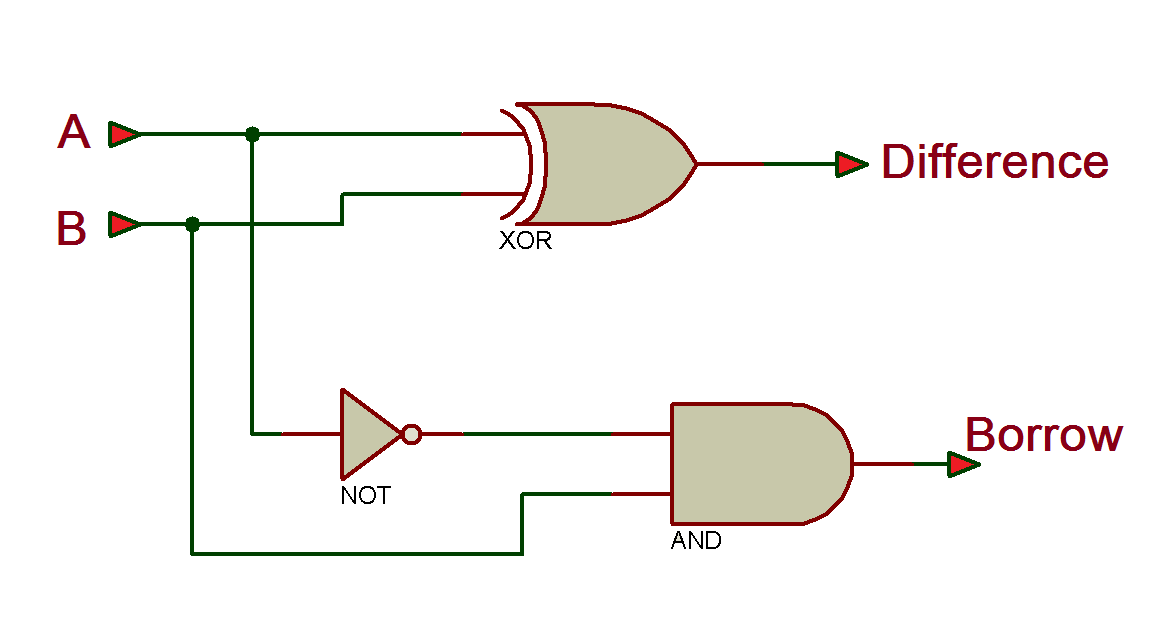
Half-subtractor circuit

Truth table

Next, let’s write the VHDL program, compile and simulate it, and get the output in a waveform. We’ll also verify the output waveforms with the given truth table.

First, it’s important to review the step-by-step procedure provided in VHDL Tutorial – 3. In that tutorial, we learn how to design a project, edit and compile a program, create a waveform file, simulate the program, and generate the final output waveforms.

VHDL program

Gate-level modeling:

module half_sub(a,b,bo,dif);
  input a,b;
  output bo,dif;
  wire a_not;

   not(a_not,a);
   xor(dif,a,b);
   and(bo,a_not,b);
endmodule;

Dataflow modeling:

module half_sub(a,b,bo,dif);
  input a,b;
  output bo,dif;

       assign dif = a ^ b;

       assign bo = ~a & b;
endmodule

Now, compile the above program, creating a waveform file with all of the necessary inputs and outputs that are listed, and simulate the project. 

Here are the results…

Waveform simulation

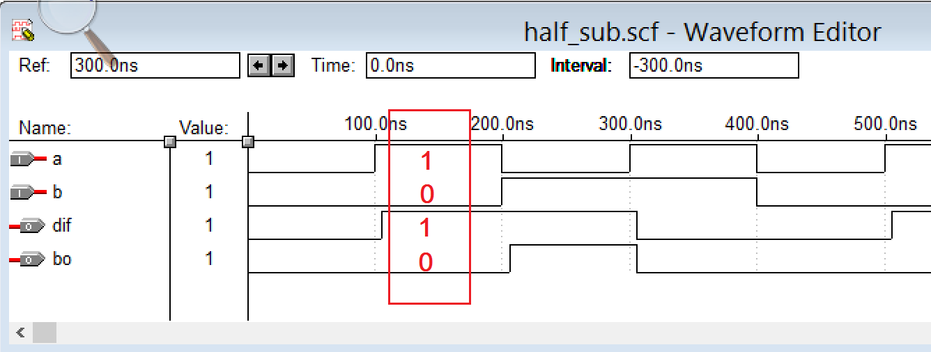
Be sure to verify the ‘dif’ and ‘bo’ output waveforms with the given truth table. For the ‘a=1’ and ‘b=0’ inputs, the outputs are ‘bo=0’ and ‘dif=1,’ as highlighted in the above figure.

Next, let’s move on to the full-subtractor-circuit design.

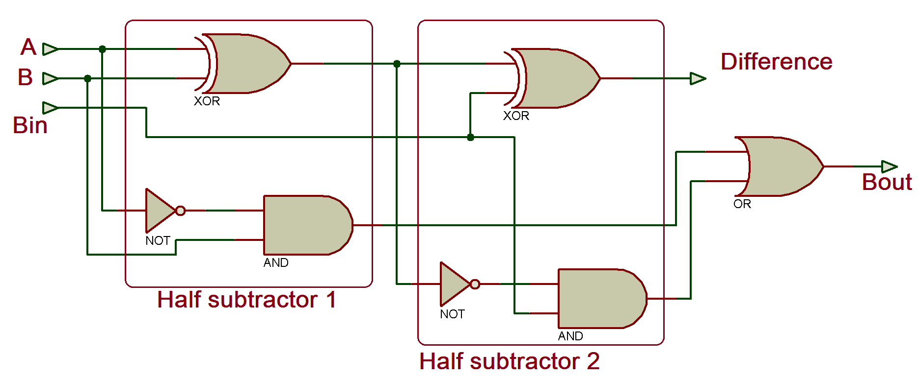
Full-subtractor circuit

Truth table

Verilog program

Gate-level modeling:

module full_sub(a,b,bin,dif,bout);
  input a,b,bin;
  output dif,bout;
  wire a_not,t1,t1_not,t2,t3;  

  xor(t1,a,b)
  not(a_not,a);
  not(t1_not,t1);
  and(t2,a_not,b);
  and(t3,t1_not,bin);
  or(bout,t2,t3);
endmodule   

Dataflow modeling:

module full_sub(a,b,bin,dif,bout);
  input a,b,bin;
  output dif,bout;

   assign dif = a ^ b ^ bin;
   assign bout = ~a  & (b ^ bin) | b & bin;
endmodule

Let’s now explore the same program using a different modeling style: structural modeling. We previously used this approach in the full adder circuit tutorial.

In structural modeling, the complete program is divided into smaller, reusable modules. In this example, we’ll first create a module for a half subtractor, then use it twice. This process is called module instantiation. You can instantiate a complete Verilog module within any other Verilog program — this modularity is a key strength of Verilog.

This modeling style is especially useful when building large and complex Verilog designs, as it allows you to break down the overall program into manageable submodules. These modules can then be instantiated wherever needed in the main Verilog program.

Now, let’s see how to perform module instantiation in a Verilog program.

//////////// Verilog module of half subtractor ///////////////

module half_sub(a,b,dif,bor);
 input a,b;
 output dif,bor;
 wire a_not;
 xor(dif,a,b);
 not(a_not,a);

 and(bor,a_not,b);
endmodule

////// Verilog main program of full subtractor /////////////

module full_sub(a,b,bin,dif,bout);
 input a,b,bin;
 output dif,bout;
 wire w1,w2,w3;
 half_sub HS1(a,b,w1,w2);     // module instantiation
 half_sub HS2(w1,bin,dif,w3);
 or(bout,w2,w3);
endmodule

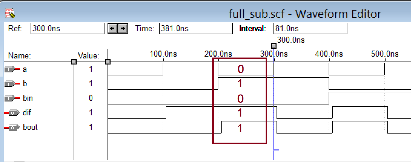
Compile the above program, creating a waveform file with all of the listed inputs and outputs, and save the waveform file. Lastly, simulate the project and you should get following result.

Waveform simulation

In the next tutorial, we’ll learn how to design circuits for an 8-bit parity generator and checker using Verilog.


You may also like:


  • Verilog Tutorial 10: How to design half and full-adder circuits…

  • How to design a digital circuit for a Boolean equation…

  • How to use NOR as the universal gate in Verilog

  • How to design, simulate, and verify all digital gates in…

  • How to compile, simulate, and verify a Verilog program using…

  • What is Verilog, its features, and design flow?- Part 2

  • What are the fundamentals of Verilog programs?-Part 1

  • How to design a digital circuit using VHDL

Filed Under: Tutorials
Tagged With: circuits, fullsubtractor, halfsubtractor, simulation, subtractor, tutorial, verilog
 

Next Article

← Previous Article
Next Article →

Questions related to this article?
👉Ask and discuss on Electro-Tech-Online.com and EDAboard.com forums.


Tell Us What You Think!! Cancel reply

You must be logged in to post a comment.

EE TECH TOOLBOX

“ee
Tech Toolbox: Internet of Things
Explore practical strategies for minimizing attack surfaces, managing memory efficiently, and securing firmware. Download now to ensure your IoT implementations remain secure, efficient, and future-ready.

EE Learning Center

EE Learning Center
“engineers
EXPAND YOUR KNOWLEDGE AND STAY CONNECTED
Get the latest info on technologies, tools and strategies for EE professionals.

HAVE A QUESTION?

Have a technical question about an article or other engineering questions? Check out our engineering forums EDABoard.com and Electro-Tech-Online.com where you can get those questions asked and answered by your peers!


RSS EDABOARD.com Discussions

  • Reducing "shoot-through" in offline Full Bridge SMPS?
  • High Side current sensing
  • How to simulate power electronics converter in PSpice?
  • Voltage mode pushpull is a nonsense SMPS?
  • Layout IRN reduction in Comparator

RSS Electro-Tech-Online.com Discussions

  • Back to the old BASIC days
  • Parts required for a personal project
  • PIC KIT 3 not able to program dsPIC
  • Failure of polypropylene motor-run capacitors
  • Siemens large industrial PLC parts

Featured – RPi Python Programming (27 Part)

  • RPi Python Programming 21: The SIM900A AT commands
  • RPi Python Programming 22: Calls & SMS using a SIM900A GSM-GPRS modem
  • RPi Python Programming 23: Interfacing a NEO-6MV2 GPS module with Raspberry Pi
  • RPi Python Programming 24: I2C explained
  • RPi Python Programming 25 – Synchronous serial communication in Raspberry Pi using I2C protocol
  • RPi Python Programming 26 – Interfacing ADXL345 accelerometer sensor with Raspberry Pi

Recent Articles

  • What is AWS IoT Core and when should you use it?
  • AC-DC power supply extends voltage range to 800 V DC
  • Infineon’s inductive sensor integrates coil system driver, signal conditioning circuits and DSP
  • Arm Cortex-M23 MCU delivers 87.5 µA/MHz active mode
  • STMicroelectronics releases automotive amplifiers with in-play open-load detection

EE ENGINEERING TRAINING DAYS

engineering

Submit a Guest Post

submit a guest post
Engineers Garage
  • Analog IC TIps
  • Connector Tips
  • Battery Power Tips
  • DesignFast
  • EDABoard Forums
  • EE World Online
  • Electro-Tech-Online Forums
  • EV Engineering
  • Microcontroller Tips
  • Power Electronic Tips
  • Sensor Tips
  • Test and Measurement Tips
  • 5G Technology World
  • Subscribe to our newsletter
  • About Us
  • Contact Us
  • Advertise

Copyright © 2025 WTWH Media LLC. All Rights Reserved. The material on this site may not be reproduced, distributed, transmitted, cached or otherwise used, except with the prior written permission of WTWH Media
Privacy Policy

Search Engineers Garage

  • Electronic Projects & Tutorials
    • Electronic Projects
      • Arduino Projects
      • AVR
      • Raspberry pi
      • ESP8266
      • BeagleBone
      • 8051 Microcontroller
      • ARM
      • PIC Microcontroller
      • STM32
    • Tutorials
      • Audio Electronics
      • Battery Management
      • Brainwave
      • Electric Vehicles
      • EMI/EMC/RFI
      • Hardware Filters
      • IoT tutorials
      • Power Tutorials
      • Python
      • Sensors
      • USB
      • VHDL
    • Circuit Design
    • Project Videos
    • Components
  • Articles
    • Tech Articles
    • Insight
    • Invention Stories
    • How to
    • What Is
  • News
    • Electronic Product News
    • Business News
    • Company/Start-up News
    • DIY Reviews
    • Guest Post
  • Forums
    • EDABoard.com
    • Electro-Tech-Online
    • EG Forum Archive
  • DigiKey Store
    • Cables, Wires
    • Connectors, Interconnect
    • Discrete
    • Electromechanical
    • Embedded Computers
    • Enclosures, Hardware, Office
    • Integrated Circuits (ICs)
    • Isolators
    • LED/Optoelectronics
    • Passive
    • Power, Circuit Protection
    • Programmers
    • RF, Wireless
    • Semiconductors
    • Sensors, Transducers
    • Test Products
    • Tools
  • Learn
    • eBooks/Tech Tips
    • Design Guides
    • Learning Center
    • Tech Toolboxes
    • Webinars & Digital Events
  • Resources
    • Digital Issues
    • EE Training Days
    • LEAP Awards
    • Podcasts
    • Webinars / Digital Events
    • White Papers
    • Engineering Diversity & Inclusion
    • DesignFast
  • Guest Post Guidelines
  • Advertise
  • Subscribe