Selecting components is one of the most essential and critical processes when designing any electronic system. Poor component selection can lead to many problems within the design, PCB layout, power budget, etc. In this article, we will discuss how to select a component for a low-power-optimized design.
Resistor
The power dissipated by a resistor is in the form of heat. When the current flows through it, the resistor is heated. The primary selection properties of a resistor are resistance, power rating, composition, temperature coefficient, operating temperature, thermal resistance, etc. For our purposes here, we will discuss the properties that cause the power dissipation in resistors.
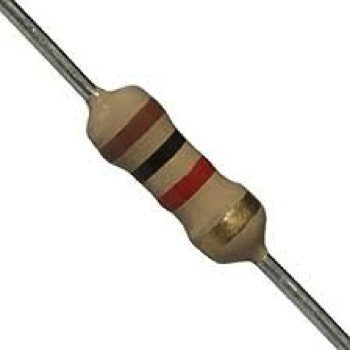
Fig 1: Resistor
Power Rating: Power rating is the maximum power that can be dissipated from the resistor without destroying the device. The rate of conversion is the power of dissipation. For example, if a resistor has a power rating of ¼ Watts, then ¼ Watts is the maximum amount of power that should be fed into the resistor.
Let’s take another example. Here, we have an 800Ω resistor with a voltage of 12 volts powering the circuit to light an LED. The power that the circuit would be delivering is:
P=V2/R
Where V is the voltage across the resistor and R is its resistance.
P = 12*12/800 = 0.18W
Therefore, we should always ensure that the resistor’s power rating meets the circuit requirements.
Thermal Resistance (Rθ): The factor of proportionality between power dissipation and over-temperature and is usually expressed as
Rθ = dT/P
where Rθ is the thermal resistance, dT is the temperature change, and P is the power dissipated. A lower value of Rθ indicates that the heat energy will be transferred more freely and offer better power performance. So, the value of Rθ should be low while selecting a resistor.
Composition: There are different compositions of the resistors, but lead (4.55×10⁶ S/m) has lower thermal conductivity than copper (5.96×10⁷ S/m) and does not dissipate heat as copper does. So, we should choose the resistor with the composition of lead wire. Lead resistors are more expensive than copper resistors which limit their use.
Other ways to minimize the power dissipation in the context of a resistor are the following:
- While designing a PCB, heavy copper traces or ground planes (which act as heatsinks) reduce the temperature rise wires and solder joints. Therefore, we should provide good ground planes and heavy copper traces to minimize heat dissipation.
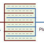
Let’s take an example of a voltage divider that gives an output of 9V from 12V:
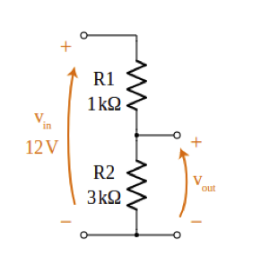
Fig: 2 Voltage Divider Circuit
The equation to find the output voltage of a divider circuit:
Vout = (R2/R1 + R2) * Vin
Where Vout is the output voltage, Vin is the input voltage, and R1 and R2 are the resistance of resistors R1 and R2.
Vin = 12V, R1= 1K, R2= 3K
Vout = (3K /( 1K + 3K)) * 12V
Vout = 9V
Now current through the circuit will be:
I = Vin / (R1+ R2)
I = 12 /( 1K + 3K) = 3mA
P = IV = 3mA*12V=36mW
If we take the values of R1= 10K and R2= 30K then:
Vout = (30K / (10K + 30K))* 12V = 9V
I = 12 / (10K + 30K) = 0.3mA
P = IV = 0.3mA*12V=3.6mW
By increasing the value of the resistor in voltage divider circuits, LED drive circuits can reduce power consumption.
Capacitor
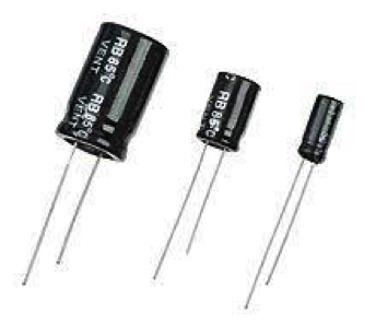
Fig: 3 Capacitor
The power dissipated by a capacitor results from its ESR, leakage current, etc. The major properties of a capacitor are capacitance, ESR, tolerance, rated voltage, temperature coefficient, operating temperature, and leakage current. Several parameters are important to keep in mind while selecting a capacitor.
- ESR (Equivalent Series Resistance): The ESR (also known as the internal resistance of capacitor) of the capacitor is responsible for the energy dissipated as heat and is directly proportional to the DF (Dissipation Factor).
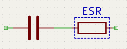
Fig: 4 ESR Model
ESR = XC * DF
XC = 1/ (2 * PI * f * C)
where XC is capacitive reactance, DF is dissipation Factor, C is the capacitance, and f is the frequency.
ESR is frequency-dependent, making it a “DYNAMIC” quantity. The ESR is caused by many factors, such as Ohmic losses in the leads and plates themselves, as well as losses in the dielectric material used between the capacitor plates.
A high ESR value degrades the performance as the capacitor will have less ability to pass current to and from its plates to the external circuit because of their longer charging and discharging RC time constant. The ESR of a capacitor needs to be as low as possible for all electronic circuit designs so that the operation of the capacitor is as near to the ideal as possible.
- Capacitor’s Leakage Current: The dielectric used inside the capacitor to separate the conductive plates is not a perfect insulator. When the constant supply voltage is applied to a capacitor, the powerful electric fields built up by the charge on the plates result in a minimal current leaking through the dielectric. The amount of leakage current varies by the size of the capacitor. Typically, tantalum and electrolytic caps have high leakage current, and ceramic and film capacitors have low leakage current.

Fig: 5 Leakage Model
When selecting capacitors for a low-power embedded system, it is best to choose capacitors with low leakage current.
- Rated Voltage: The rated voltage is another important characteristic that defines the maximum continuous voltage, either DC or AC, that can be applied to the capacitor without failure during its working life. Any voltage above its working voltage may cause failure, which is determined by the failure rate. A capacitor will have a longer working life if operated in a cool environment and within its rated voltage. Always use a capacitor with a rated voltage equal to or exceeding the circuit’s applied voltage.
Inductor
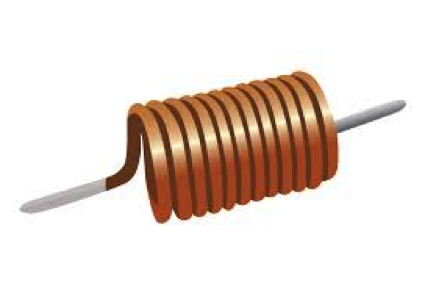
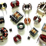
Fig: 6 Inductor
Power dissipation in an inductor occurs in the windings and the core, termed windings loss and core loss. The significant properties of an inductor are material core, inductance, tolerance, current rating, shielding, DC resistance, Q, self-resonant frequency, operating temperature, and inductance frequency. The following are important parameters to keep in mind when selecting an inductor.
- Q factor, or Quality Factor: This refers to the ratio of the reactance of the coil to its resistance. This value is frequency-dependent (Q=2πf L/R). As f is the frequency of the current flowing through the coil, the Q value will differ according to the frequency. The higher Q value will cause lower losses and better suitability for use as a high-frequency inductor.
- Self Resonant Frequency (SRF): This describes the frequency at which an inductor stops working as an inductor. The self-resonant frequency can be expressed as:
SRF = 1 / 2 * PI * √LC
where L is the inductance and C is the parasitic capacitance.
This value should be higher than the frequency of the application. It would be best to consider that the self-resonant frequency must be sufficiently higher than the usage frequency.
- Saturation Current: This refers to the DC current, which causes the inductance to drop by a specified value. In addition, when an inductor can no longer store energy and instead shows a drop in energy storage and inductance, it has reached saturation point. The inductance drops because the core can only store a certain amount of magnetic flux density. The core material and wire insulation can be damaged at high temperatures if the current goes high enough during operation. In most cases, the operation of an inductor is limited by its temperature rise.
- DC Resistance (DCR): During the flow of DC supply (0 Hertz frequency), inductors provide resistance to the current flow. This resistance is referred to as DC resistance (DCR). The DCR dissipates heat and reduces efficiency just like any other resistor. In real Inductors, the Q factor is dependable in DCR. The low value of DCR is essential for less power dissipation. It is best to use the inductor in given ambient temperature conditions to operate them in the minimum DCR value region.
- Material Core: The core must be large enough and low enough permeability to avoid saturation (or shift in inductance below the minimum required level.) This basic formula defines the power loss of an inductor:
Ploss = Pcore(Core Loss) + Pdcr(Wire loss by dc Resistance) + Pacr(Wire loss by ac Resistance).
Here we will talk about the core loss.
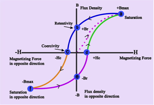
Fig: 7 Hysteresis Curve
Hysteresis is the common property of ferromagnetic substances. The effect due to which the magnetization of ferromagnetic materials lags behind the magnetic field is described as the hysteresis effect. The hysteresis loop area above in the figure represents energy loss. Power loss depends on the number of times per second the hysteresis loop is traversed. Thus, hysteresis loss varies directly with frequency. Most commercial power-supply inductors are gapped ferrites (Figure 7), which are typically not low-loss materials and will generally not perform well in low-power, high-frequency applications. When designing inductors for low losses, use low-permeability materials to get the B field (magnetic field B is a field produced by electric charges in motion) down, choose low-loss core materials, and consider using Litz wire(multistrand wire).
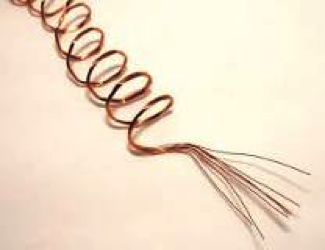
Fig: 8 Litz wire
MOSFET
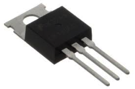
Fig: 9 Mosfet
Power dissipation in a MOSFET is mainly divided into two forms: resistive power dissipation and switching power dissipation. The internal resistance of MOSFET causes resistive loss, and switching loss is the power loss during switching MOSFETs on and off stage. Below are some of the important parameters to keep in mind while selecting a MOSFET:
- Max drain to source voltage (VDS): The drain-source voltage VDS rating is important in selecting MOSFETs. Choose MOSFETs with a VDS (drain-source voltage) sufficiently higher than the voltage at which they will be used, as voltage exceeding VDS might destroy a MOSFET. But with a high value of VDS higher, the RDS (on-state resistance) results in conduction loss. Both parameters should be taken care of while selecting MOSFET.
- Drain Source On Resistance RDS(ON): RDS is the resistance value between the drain and source of a MOSFET during operation (ON). The RDS of MOSFETs is low when they operate in the linear region. For switching applications, we can reduce the on-state resistance by using MOSFETs in the low VDS region, thereby reducing power loss. The amount of current that MOSFETs can handle is limited by the value of VGS. Also, the higher the temperature, the higher the RDS(ON) value becomes, so it is important to consider temperature too.
- Maximum DC drain current: This is the maximum current a device can withstand indefinitely given adequate cooling. Depending on the VDS, the device may only be able to conduct a small fraction of this current before failure. The only way to be sure the device can withstand the desired current is to refer to the safe operating area curve in the device’s datasheet.
- Considerations for VGS: MOSFETs turn on when the VGS (gate-source voltage) exceeds their threshold voltage Vth. Choose a value for VGS that should be higher than Vth. The higher the VGS, the lower the RDS(ON) value. Selecting the optimal gate voltage is therefore critical.
- Switching Speed: Switching losses are present at a higher frequency. To reduce these losses for high-frequency, high-speed power MOSFETs should be used. Compared to insulated-gate bipolar transistors (IGBT) and thyristors, power MOSFETs have very high switching speeds and improved efficiency at low voltages.
DC/DC converters
Different types of DC/DC converters include buck, boost, and flyback. Buck converters are used to step down the voltages, while boost converters are used to step-up the voltages. The flyback converter is a buck-boost converter that can step the voltage up or down. Many factors should be considered for designing DC/DC converters, such as power efficiency, transient response, input-output voltage relation, efficiency, input-output isolation, input voltage range, maximum output current, DC line/load regulation, and other factors. Below are some of the parameters to keep in mind while selecting a converter
- Input Voltage (VIN) Range Parameter: The input voltage range is the converter’s maximum and minimum allowable input supply. If the Input supply exceeds the maximum allowable input, the converter can be damaged.
- Maximum Output Current (IOUT) Parameter: This parameter is the maximum output current the converter can provide while meeting the other parameters.
- Quiescent Current (IQ) Parameter: Quiescent current is the current used to operate the converter and is not delivered to the load. It is measured when the converter is enabled, and the output/load current is zero. A low quiescent current maximizes the converter output efficiency, reduces heat, and extends battery life in battery-operated applications. Choose low IQ current when selecting a DC/DC converter.
- Efficiency Parameter: Power efficiency is defined as the percentage of the input power delivered to the output. It is expressed as:
Efficiency = 100 * (Iout * Vout) / (Iin * Vin)
An ideal switching converter can approach 100% efficiency. The loss in converters includes switching loss and inductor loss. Power dissipation should be minimized to maximize efficiency.
- Switching Frequency: DC/DC converter circuits have their unique switching frequencies. A higher switching frequency makes it possible to use smaller inductors and capacitors and improves the step load behavior of the converter. A higher switching frequency also increases switching losses, extending the EMI radiation frequency range.
You may also like:


Filed Under: IoT tutorials, Tutorials
Questions related to this article?
👉Ask and discuss on EDAboard.com and Electro-Tech-Online.com forums.
Tell Us What You Think!!
You must be logged in to post a comment.