Engineers Garage

  • Electronic Projects & Tutorials
    • Electronic Projects
      • Arduino Projects
      • AVR
      • Raspberry pi
      • ESP8266
      • BeagleBone
      • 8051 Microcontroller
      • ARM
      • PIC Microcontroller
      • STM32
    • Tutorials
      • Audio Electronics
      • Battery Management
      • Brainwave
      • Electric Vehicles
      • EMI/EMC/RFI
      • Hardware Filters
      • IoT tutorials
      • Power Tutorials
      • Python
      • Sensors
      • USB
      • VHDL
    • Circuit Design
    • Project Videos
    • Components
  • Articles
    • Tech Articles
    • Insight
    • Invention Stories
    • How to
    • What Is
  • News
    • Electronic Product News
    • Business News
    • Company/Start-up News
    • DIY Reviews
    • Guest Post
  • Forums
    • EDABoard.com
    • Electro-Tech-Online
    • EG Forum Archive
  • DigiKey Store
    • Cables, Wires
    • Connectors, Interconnect
    • Discrete
    • Electromechanical
    • Embedded Computers
    • Enclosures, Hardware, Office
    • Integrated Circuits (ICs)
    • Isolators
    • LED/Optoelectronics
    • Passive
    • Power, Circuit Protection
    • Programmers
    • RF, Wireless
    • Semiconductors
    • Sensors, Transducers
    • Test Products
    • Tools
  • Learn
    • eBooks/Tech Tips
    • Design Guides
    • Learning Center
    • Tech Toolboxes
    • Webinars & Digital Events
  • Resources
    • Digital Issues
    • EE Training Days
    • LEAP Awards
    • Podcasts
    • Webinars / Digital Events
    • White Papers
    • Engineering Diversity & Inclusion
    • DesignFast
  • Guest Post Guidelines
  • Advertise
  • Subscribe

How to use the TCS230/TCS3200 color-recognition sensor with Arduino

By Nikhil Agnihotri June 19, 2024

Color detection is the process of identifying and distinguishing colors within an image, video, scene, or object. Many embedded and robotic applications require this feature, as it’s useful for sorting, selection, test strip reading, path determination, and more. 

Two standard sensors used for color detection include TCS230 or TCS3200. TCS3200 recognizes various colors based on their wavelength and is easy to interface with any microcontroller using GPIO. TCS230 is slightly more sensitive, detecting a narrower range of colors with higher precision.

In this project, we’ll interface the TCS230/TCS3200 sensor (either can be used) with Arduino Mega, calibrate the sensor, and derive the RGB values for specific colors. 

Components required

  1. Arduino UNO/Arduino Mega x1
  2. TCS230/TCS3200 color sensor x1
  3. Connecting/DuPont wires

The color-recognition sensors
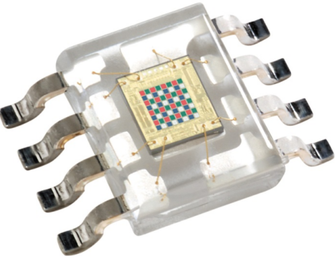
TCS230 and TCS3200 sensors detect and measure the intensity of light across different wavelengths to determine the color of an object. They can detect various colors using an array of photodiodes with different filters. 

TCS230/TCS3200 contains four white LEDs that light up the object in front of it. 

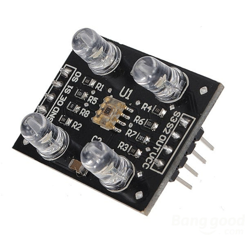
Typically, color-recognition sensors have four channels: red, green, blue, and clear (no filter). The TCS3200 has an array of photodiodes with four filters. In total, it has 16 photodiodes with red, green, and blue filters that are sensitive to red, green, and blue wavelengths; and it has 16 photodiodes without filters.

These sensors control the integration time during which they collect light. This allows them flexibility in adapting to different lighting conditions for greater color-recognition accuracy. TCS230/TCS3200 provide analog output signals proportional to each color channel’s light intensity. They also have a frequency-to-voltage converter that converts the color information into a voltage signal, which can be easily measured.

Additionally, TCS230/TCS3200 uses a modulation and filtering technique to eliminate ambient light interference, further improving the accuracy of color detection. By selectively choosing the photodiode filter readings, the strength of colors can be identified.

These sensors operate at a voltage of 2.7~5.5V DC and have the below pin diagram.

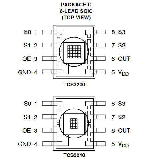
Description of the TCS230/TCS3200 pin configuration:

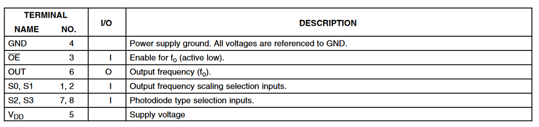
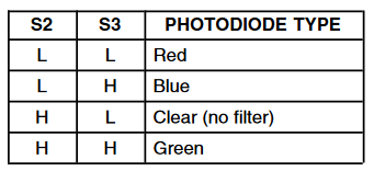
Pins S2 and S3 are used to read the light intensity of a particular color. The photodiodes are connected in parallel, so setting S2 and S3 to LOW and HIGH in different combinations allows the photodiodes to be matched to the corresponding colors.

The colors are selected as per the following table.

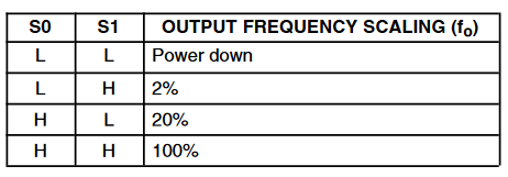
Pins S0 and Si scale the output frequency to 100%, 20%, or 2% of the preset parameters. Scaling the output optimizes the sensor readings for different microcontrollers or frequency counters.

When using Arduino, 20% is typical. Scaling using pins S0 and S1 is done according to the following table.
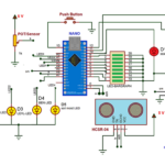
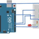
Circuit connections
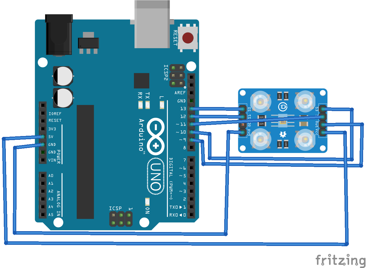
For this project, we’ll connect the TCS230/TCS3200 color sensor with the Arduino Mega as follows:

  • Connect TCS230/TCS3200’s S0, S1, S2, S3, and ouput pins of with Arduino’s GPIO13, GPIO12, GPIO11, GPIO10, and GPIO9, respectively.
  • Next connect TCS230/TCS3200’s VCC and GND pins with Arduino’s 5Vout and ground pins, respectively.


Arduino sketch

How it works
Arduino reads the light intensity of each color using the TCS230/TCS3200 sensor by choosing the red, green, and blue channels one after the other. The “read” values are mapped to their appropriate calibrated values for an RBG color output. Note that the RGB color value is only obtained after calibration. 

The sensor is affected by ambient light. So, the color-detection calibration is only possible after the ambient light calibration. These RGB values do not match the true RGB color values, but they’re a decent estimate and valuable for sorting or selecting objects. 

Calibration
The TCS230/TCS3200 sensor must be calibrated in the same light in which it will be used. Print the red (#FF0000), green (#00FF00), and blue (#0000FF) colors on a sheet, along with a color for testing as shown in the image below.

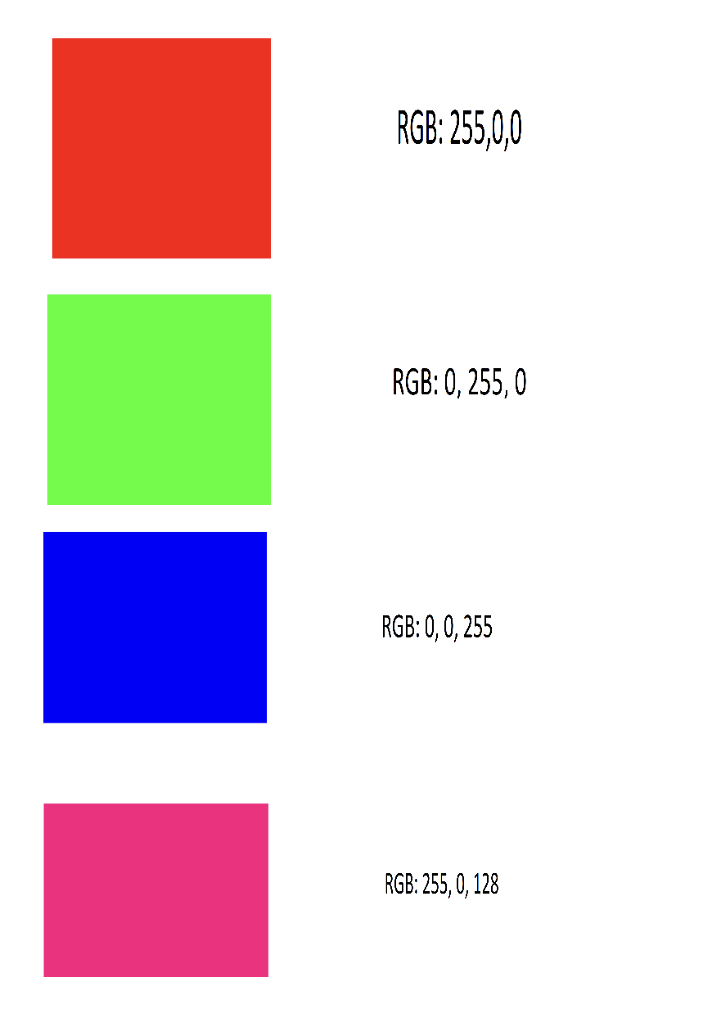
First, put the sensor on the “true red” color and note the readings for the red, green, and blue channels. Repeat for the “true green” and “true blue” colors.

When the sensor is on the true red color, the frequency output of the red channel will be at its lowest. When it’s on true green or true blue, the frequency output will be at its highest for either color. The lowest frequency is mapped at 255 and the highest recorded frequency is mapped at 0.

After obtaining each color’s minimum and maximum values, map them in the sketch using the map() function. This is already done in the sketch above. But you’ll need to do so based on the lighting in your environment. This way, the sensor will be calibrated for the ambient light conditions in your project’s operating conditions.

The code
The sketch begins by defining the pin assignments for the TCS230/TCS3200 color sensor. Next, the variables are declared for storing the RGB values. In the setup() function, the pins connected to S0, S1, S2, and S3 are set as digital outputs, and the pin connected to TCS230/TCS3200 is set as a digital input. The S0 pin is set to HIGH, and the S1 is set to LOW — selecting for 20% scaling, which is most suitable for Arduino. The baud rate for the serial communication is set to 9600 bps. 

In the loop() function, Arduino first selects the sensor’s red channel by setting the S2 and S3 pins to LOW. It reads the frequency of the red color, mapping to its calibrated values using the map function. The value for the red filter is printed to the serial port. Arduino then selects the sensor’s green channel by setting the S2 and S3 pins to HIGH. It reads the frequency of the green color, mapping to its calibrated values using the map function. The value for the green filter is printed to the serial port. 

Lastly, Arduino selects the sensor’s blue channel by setting the S2 pin to LOW and the S3 pin to HIGH. It reads the frequency of the blue color, mapping to its calibrated values using the map function. The value for the blue filter is printed to the serial port. 

This provides an approximate RGB color value, which is useful in selecting or sorting objects. 

Video demonstration


You may also like:

  • beginners guide
    Basic Electronics 01 – Beginners guide to setting up an…
  • IR LEDs
    Arduino-based optical proximity sensor using IR LEDs

  • How to design a multi-use level indicator using Arduino

  • What is IFTTT and how does it work?

  • How to use Arduino’s analog comparator

Filed Under: Arduino Projects, Electronic Projects, Featured Contributions, Video
Tagged With: Arduino, color, colordetection, electronicprojects, sensors, tcs230, tcs3200
 

Next Article

← Previous Article
Next Article →

Questions related to this article?
👉Ask and discuss on Electro-Tech-Online.com and EDAboard.com forums.


Tell Us What You Think!! Cancel reply

You must be logged in to post a comment.

EE TECH TOOLBOX

“ee
Tech Toolbox: Internet of Things
Explore practical strategies for minimizing attack surfaces, managing memory efficiently, and securing firmware. Download now to ensure your IoT implementations remain secure, efficient, and future-ready.

EE Learning Center

EE Learning Center
“engineers
EXPAND YOUR KNOWLEDGE AND STAY CONNECTED
Get the latest info on technologies, tools and strategies for EE professionals.

HAVE A QUESTION?

Have a technical question about an article or other engineering questions? Check out our engineering forums EDABoard.com and Electro-Tech-Online.com where you can get those questions asked and answered by your peers!


RSS EDABOARD.com Discussions

  • Reducing "shoot-through" in offline Full Bridge SMPS?
  • High Side current sensing
  • How to simulate power electronics converter in PSpice?
  • Voltage mode pushpull is a nonsense SMPS?
  • Layout IRN reduction in Comparator

RSS Electro-Tech-Online.com Discussions

  • Back to the old BASIC days
  • Parts required for a personal project
  • PIC KIT 3 not able to program dsPIC
  • Failure of polypropylene motor-run capacitors
  • Siemens large industrial PLC parts

Featured – RPi Python Programming (27 Part)

  • RPi Python Programming 21: The SIM900A AT commands
  • RPi Python Programming 22: Calls & SMS using a SIM900A GSM-GPRS modem
  • RPi Python Programming 23: Interfacing a NEO-6MV2 GPS module with Raspberry Pi
  • RPi Python Programming 24: I2C explained
  • RPi Python Programming 25 – Synchronous serial communication in Raspberry Pi using I2C protocol
  • RPi Python Programming 26 – Interfacing ADXL345 accelerometer sensor with Raspberry Pi

Recent Articles

  • What is AWS IoT Core and when should you use it?
  • AC-DC power supply extends voltage range to 800 V DC
  • Infineon’s inductive sensor integrates coil system driver, signal conditioning circuits and DSP
  • Arm Cortex-M23 MCU delivers 87.5 µA/MHz active mode
  • STMicroelectronics releases automotive amplifiers with in-play open-load detection

EE ENGINEERING TRAINING DAYS

engineering

Submit a Guest Post

submit a guest post
Engineers Garage
  • Analog IC TIps
  • Connector Tips
  • Battery Power Tips
  • DesignFast
  • EDABoard Forums
  • EE World Online
  • Electro-Tech-Online Forums
  • EV Engineering
  • Microcontroller Tips
  • Power Electronic Tips
  • Sensor Tips
  • Test and Measurement Tips
  • 5G Technology World
  • Subscribe to our newsletter
  • About Us
  • Contact Us
  • Advertise

Copyright © 2025 WTWH Media LLC. All Rights Reserved. The material on this site may not be reproduced, distributed, transmitted, cached or otherwise used, except with the prior written permission of WTWH Media
Privacy Policy

Search Engineers Garage

  • Electronic Projects & Tutorials
    • Electronic Projects
      • Arduino Projects
      • AVR
      • Raspberry pi
      • ESP8266
      • BeagleBone
      • 8051 Microcontroller
      • ARM
      • PIC Microcontroller
      • STM32
    • Tutorials
      • Audio Electronics
      • Battery Management
      • Brainwave
      • Electric Vehicles
      • EMI/EMC/RFI
      • Hardware Filters
      • IoT tutorials
      • Power Tutorials
      • Python
      • Sensors
      • USB
      • VHDL
    • Circuit Design
    • Project Videos
    • Components
  • Articles
    • Tech Articles
    • Insight
    • Invention Stories
    • How to
    • What Is
  • News
    • Electronic Product News
    • Business News
    • Company/Start-up News
    • DIY Reviews
    • Guest Post
  • Forums
    • EDABoard.com
    • Electro-Tech-Online
    • EG Forum Archive
  • DigiKey Store
    • Cables, Wires
    • Connectors, Interconnect
    • Discrete
    • Electromechanical
    • Embedded Computers
    • Enclosures, Hardware, Office
    • Integrated Circuits (ICs)
    • Isolators
    • LED/Optoelectronics
    • Passive
    • Power, Circuit Protection
    • Programmers
    • RF, Wireless
    • Semiconductors
    • Sensors, Transducers
    • Test Products
    • Tools
  • Learn
    • eBooks/Tech Tips
    • Design Guides
    • Learning Center
    • Tech Toolboxes
    • Webinars & Digital Events
  • Resources
    • Digital Issues
    • EE Training Days
    • LEAP Awards
    • Podcasts
    • Webinars / Digital Events
    • White Papers
    • Engineering Diversity & Inclusion
    • DesignFast
  • Guest Post Guidelines
  • Advertise
  • Subscribe