Engineers Garage

  • Electronic Projects & Tutorials
    • Electronic Projects
      • Arduino Projects
      • AVR
      • Raspberry pi
      • ESP8266
      • BeagleBone
      • 8051 Microcontroller
      • ARM
      • PIC Microcontroller
      • STM32
    • Tutorials
      • Audio Electronics
      • Battery Management
      • Brainwave
      • Electric Vehicles
      • EMI/EMC/RFI
      • Hardware Filters
      • IoT tutorials
      • Power Tutorials
      • Python
      • Sensors
      • USB
      • VHDL
    • Circuit Design
    • Project Videos
    • Components
  • Articles
    • Tech Articles
    • Insight
    • Invention Stories
    • How to
    • What Is
  • News
    • Electronic Product News
    • Business News
    • Company/Start-up News
    • DIY Reviews
    • Guest Post
  • Forums
    • EDABoard.com
    • Electro-Tech-Online
    • EG Forum Archive
  • DigiKey Store
    • Cables, Wires
    • Connectors, Interconnect
    • Discrete
    • Electromechanical
    • Embedded Computers
    • Enclosures, Hardware, Office
    • Integrated Circuits (ICs)
    • Isolators
    • LED/Optoelectronics
    • Passive
    • Power, Circuit Protection
    • Programmers
    • RF, Wireless
    • Semiconductors
    • Sensors, Transducers
    • Test Products
    • Tools
  • Learn
    • eBooks/Tech Tips
    • Design Guides
    • Learning Center
    • Tech Toolboxes
    • Webinars & Digital Events
  • Resources
    • Digital Issues
    • EE Training Days
    • LEAP Awards
    • Podcasts
    • Webinars / Digital Events
    • White Papers
    • Engineering Diversity & Inclusion
    • DesignFast
  • Guest Post Guidelines
  • Advertise
  • Subscribe

Arduino piezo buzzer alarm with LDR(light dependent resistor)/photoresistor

By EG Projects June 19, 2024

This is a simple project on arduino, ldr(light dependent resistor)/photoresistor sensor and piezo buzzer. Piezo buzzer output sound level will variate by arduino depending on the intensity of light thrown on ldr/light sensor. An led will also fade by arduino depending on the intensity of light thrown on photoresistor. The diy project is same like basic electronics project which we design in our electronics class “Light sensor” using passive components(Resistors, Transistors, LDR, Led, Buzzer). The difference is, in our diy project we are going to use a dedicated microcontroller(Arduino uno) for controlling buzzer sound level and led fadeness depending on the ldr light sensor value.        

Buzzer Arduino led and LDR

Buzzer Arduino led and LDR

Piezo buzzer

Piezo buzzer is a small electronic component. It outputs a tone when voltage is supplied across its power pins. Normally piezo buzzer operates on 5 volts, but 12 volt versions are also available. The tone/sound produced by piezo buzzer depends on the power supplied to it. If power is low the output tone will be low and if power is high the pitch of tone/sound will be high. A 5 volt rated piezo buzzer can output a tone at 3 volt. The output tone pitch increase if we increase the voltage from 3 and the maximum tone we will get is at 5 volts. Piezo buzzer have two pins. Vcc to which we supply +ve voltage and Gnd which we connect to out power source ground.

LDR(Light dependent resistor)/Photoresistor

LDR is a special resistor. LDR resistance varies when light is thrown on it  Its resistance increases and decreases depending on the intensity of light thrown on it. Normally it has high resistance and when it is exposed to light its resistance decreases. This unique feature of LDR makes us to use it in automatic street light on/off circuits. It is used as autonomous light switch. Light intensity and brightness can be controlled using LDR.
In our project we are also going to measure the intensity of light with ldr(light dependent resistor). Now how we are going to measure it? See the diagram on below.

LDR Arduino measuring intensity of light

LDR Arduino measuring intensity of light
A voltage divider circuit is shown above. Recall LDR is a resistor. when their is no light on ldr very little amount of current will flow through the circuit. 100 k resistor will be on 0 potential. Their will be no voltage across the 100 k resistor. Now when a light source is brought near the LDR. Its resistance will start decreasing and current starts flowing through the circuit. Voltage starts appearing across the 100 k resistor. The more the intensity of light thrown on ldr the more voltage appears on the 100 k resistor. When the amount of light thrown on the ldr sensor increases the threshold value the ldr resistance becomes almost to 0.
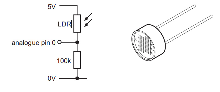
The voltage appearing across the 100 k resistor is read by the analog pins of arduino and translated for further use(controlling buzzer arduino and led fade mechanism).

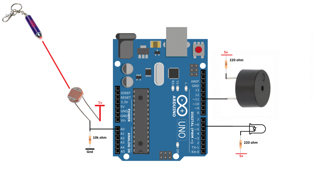
Project Circuit diagram

Arduino two digital pins and one analog pin is used in the project. Two digital pins of arduino are carefully selected. I choose the arduino digital pins(~11 and ~6) which can output a pwm signal. I hope you people know about the PWM(Pulse width modulation) technique. If not then just for this tutorial take it(pwm) as a way to output a variable signal on digital pins. From variable signal i mean output voltage between 0-5 volt. It can be 0.5, 1, 1.2, 3.5, 4.1 volts any voltage between 0-5 volts.
Arduino buzzer one leg is connected to arduino pin#11 and the other is pulled high. Led positive leg is connected to arduino pin#6 and the other end is pulled high. 5 volts supplied to buzzer and led can be from the arduino 5v pin. 220 ohm resistor in series with the buzzer and led is used for current limiting purpose.
LDR and 10 k resistor voltage divider circuit middle point is connected to analog channel 0 of arduino uno. Ldr input 5 volts can also be supplied with the arduino 5 volt output rail. Circuit diagram of the project is given below.  

Arduino buzzer alarm with light dependent resistor(LDR)/photoresistor

Arduino buzzer alarm with light dependent resistor(LDR)/photoresistor
Coming to the code portion of the project. Code is written in arduino ide and its free for every one. You can use and modify it according to your needs. In the code first i defined the variables for analog channel 0 of arduino as sensor, buzzer arduino pin(arduino pin#11) as Buz and led arduino pin(arduinp pin#6) as Led. In the setup function i declared the Buz and Led pins as output. Since they are outputting voltage or Pwm(pulse width modulated) signal for buzzer and led fadness.
In setup function arduino serial port is also initialized at 9600 baud rate. Arduino serial port is initialized to see the voltage measurement by analog channel 0 to which LDR output is connected. Serial.begin(9600) statement is initialing the arduino serial port.     

In the loop function first i am reading the LDR intensity light value. The statement int senValue=analogRead(sensor) is reading the LDR output voltage across 10 k resistor. The read value is stored in senValue variable. 

  • Arduino is a 5 volt tolerant device. Its gpio pins can output 5 volt TTL signal. Similarly its gpio pins can be exposed to 5 v TTL signal as input. Higher than 5 v may destroy the gpio pin. So your input voltage to arduino pins must remain between 0-5 volts. I supplied 5 volt to LDR keeping in mind the above constraint.  
  • Arduino analog channel can also read max 5 volts. Arduino ADC(Analog to digital channel) is 10 bit wide or its resolution is 10 bit. Means it can  output value up to 1024. 1024 represents 5 volts. 512 represents 2.5 volts and vise versa.
  • So if voltage across the 10 k resistor is 2 volts than the analog channel 0 of arduino will read it and provide us an integer value of 410. [ (410/1024)*5v = 2v ].

The same above strategy is applied in the code. When the voltage across 10 k resistor increases 1.5 volts(ADC value 310) then the buzzer and led are activated and are driven with the same voltage that appears across the 10 k resistor.  The if statement in the code is checking 1.5 volts or 310 integer value by ADC. Buzzer and LED will operate only on the voltages greater than 1.5 volts.     

  • Unlike arduino ADC the arduino pwm provides 8 bit resolution. So in analogWrite(*, senValue/4) function in code i am dividing the senValue by 4 to bring the senValue in 8 bit resolution 0-255. I hope it makes sense to you. 


More advanced projects involving Buzzer and a microcontroller. Click the below buttons to visit the projects. Source code and circuit diagram of each project is free.

Home security system with Arduino

WiFi security alarm with nodemcu

Download the project code. Folder contains arduino ide .ino project file. Please provide us your feed back on the project. Write your comments below in the comments section.
Code/Files

You may also like:

  • beginners guide
    Basic Electronics 01 – Beginners guide to setting up an…

  • What are the two types of hardware filters?

  • What are hardware filters and their types?

  • How do dc-dc converters work?

  • Introduction to Brain Waves & its Types (Part 1/13)

  • What are the different types of light sensors?

Filed Under: Arduino Projects, Electronic Projects, Featured Contributions


Next Article

← Previous Article
Next Article →

Questions related to this article?
👉Ask and discuss on Electro-Tech-Online.com and EDAboard.com forums.


Tell Us What You Think!! Cancel reply

You must be logged in to post a comment.

EE TECH TOOLBOX

“ee
Tech Toolbox: Internet of Things
Explore practical strategies for minimizing attack surfaces, managing memory efficiently, and securing firmware. Download now to ensure your IoT implementations remain secure, efficient, and future-ready.

EE Learning Center

EE Learning Center
“engineers
EXPAND YOUR KNOWLEDGE AND STAY CONNECTED
Get the latest info on technologies, tools and strategies for EE professionals.

HAVE A QUESTION?

Have a technical question about an article or other engineering questions? Check out our engineering forums EDABoard.com and Electro-Tech-Online.com where you can get those questions asked and answered by your peers!


RSS EDABOARD.com Discussions

  • Reducing "shoot-through" in offline Full Bridge SMPS?
  • High Side current sensing
  • How to simulate power electronics converter in PSpice?
  • Voltage mode pushpull is a nonsense SMPS?
  • Layout IRN reduction in Comparator

RSS Electro-Tech-Online.com Discussions

  • Back to the old BASIC days
  • Parts required for a personal project
  • PIC KIT 3 not able to program dsPIC
  • Failure of polypropylene motor-run capacitors
  • Siemens large industrial PLC parts

Featured – RPi Python Programming (27 Part)

  • RPi Python Programming 21: The SIM900A AT commands
  • RPi Python Programming 22: Calls & SMS using a SIM900A GSM-GPRS modem
  • RPi Python Programming 23: Interfacing a NEO-6MV2 GPS module with Raspberry Pi
  • RPi Python Programming 24: I2C explained
  • RPi Python Programming 25 – Synchronous serial communication in Raspberry Pi using I2C protocol
  • RPi Python Programming 26 – Interfacing ADXL345 accelerometer sensor with Raspberry Pi

Recent Articles

  • What is AWS IoT Core and when should you use it?
  • AC-DC power supply extends voltage range to 800 V DC
  • Infineon’s inductive sensor integrates coil system driver, signal conditioning circuits and DSP
  • Arm Cortex-M23 MCU delivers 87.5 µA/MHz active mode
  • STMicroelectronics releases automotive amplifiers with in-play open-load detection

EE ENGINEERING TRAINING DAYS

engineering

Submit a Guest Post

submit a guest post
Engineers Garage
  • Analog IC TIps
  • Connector Tips
  • Battery Power Tips
  • DesignFast
  • EDABoard Forums
  • EE World Online
  • Electro-Tech-Online Forums
  • EV Engineering
  • Microcontroller Tips
  • Power Electronic Tips
  • Sensor Tips
  • Test and Measurement Tips
  • 5G Technology World
  • Subscribe to our newsletter
  • About Us
  • Contact Us
  • Advertise

Copyright © 2025 WTWH Media LLC. All Rights Reserved. The material on this site may not be reproduced, distributed, transmitted, cached or otherwise used, except with the prior written permission of WTWH Media
Privacy Policy

Search Engineers Garage

  • Electronic Projects & Tutorials
    • Electronic Projects
      • Arduino Projects
      • AVR
      • Raspberry pi
      • ESP8266
      • BeagleBone
      • 8051 Microcontroller
      • ARM
      • PIC Microcontroller
      • STM32
    • Tutorials
      • Audio Electronics
      • Battery Management
      • Brainwave
      • Electric Vehicles
      • EMI/EMC/RFI
      • Hardware Filters
      • IoT tutorials
      • Power Tutorials
      • Python
      • Sensors
      • USB
      • VHDL
    • Circuit Design
    • Project Videos
    • Components
  • Articles
    • Tech Articles
    • Insight
    • Invention Stories
    • How to
    • What Is
  • News
    • Electronic Product News
    • Business News
    • Company/Start-up News
    • DIY Reviews
    • Guest Post
  • Forums
    • EDABoard.com
    • Electro-Tech-Online
    • EG Forum Archive
  • DigiKey Store
    • Cables, Wires
    • Connectors, Interconnect
    • Discrete
    • Electromechanical
    • Embedded Computers
    • Enclosures, Hardware, Office
    • Integrated Circuits (ICs)
    • Isolators
    • LED/Optoelectronics
    • Passive
    • Power, Circuit Protection
    • Programmers
    • RF, Wireless
    • Semiconductors
    • Sensors, Transducers
    • Test Products
    • Tools
  • Learn
    • eBooks/Tech Tips
    • Design Guides
    • Learning Center
    • Tech Toolboxes
    • Webinars & Digital Events
  • Resources
    • Digital Issues
    • EE Training Days
    • LEAP Awards
    • Podcasts
    • Webinars / Digital Events
    • White Papers
    • Engineering Diversity & Inclusion
    • DesignFast
  • Guest Post Guidelines
  • Advertise
  • Subscribe