Traffic light systems are important signaling devices that regulate the flow of vehicles and pedestrians at intersections, crosswalks, and other critical areas. These systems use three primary lights — red, yellow (amber), and green — to manage traffic effectively and ensure safety.
In this project, we’ll create a traffic light system for a four-way intersection using an Arduino microcontroller, RGB LEDs, and an MAX7219 IC-based 7-segment display board. This project aims to replicate real-world traffic light operations, providing a functional and educational model of a standard traffic control system.
Components
- Arduino MEGA x1
- 7-Segments x8
- MAX7219 IC x1
- RGB LEDs x4
- Breadboard x1
- Jumper or connecting wires
The traffic light system
In this project, we’ll design a traffic light system for a four-way intersection, with each direction labeled as A, B, C, and D. The system includes red, orange (amber), and green lights, along with a timer for each direction.
At any given time, the green light will activate for only one direction, allowing traffic to flow, while the other directions remain stopped with red lights. This setup effectively manages traffic flow, similar to real-world traffic control systems.
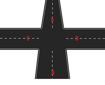
At the four-way, vehicles in intersection A are allowed to proceed first, followed by those in B, then C, and finally D. By regulating traffic in this sequence, the traffic lights follow the pattern shown in the table below, ensuring a systematic flow of vehicles and minimizing congestion at each intersection.
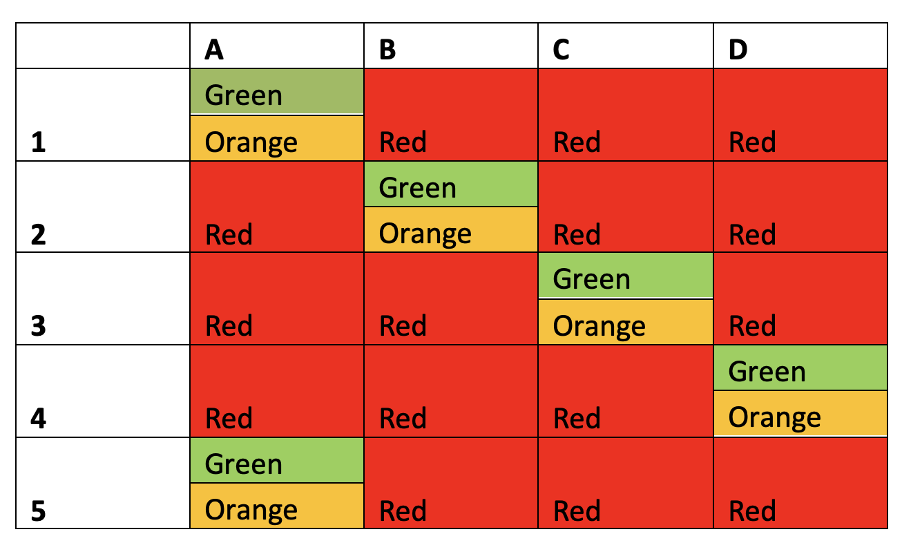
Note, that the traffic light pattern repeats itself starting from the fifth step. Assuming the green light remains active for 20 seconds for each intersection and the orange light stays on for five seconds, the traffic signal operates according to the time schedule shown below.
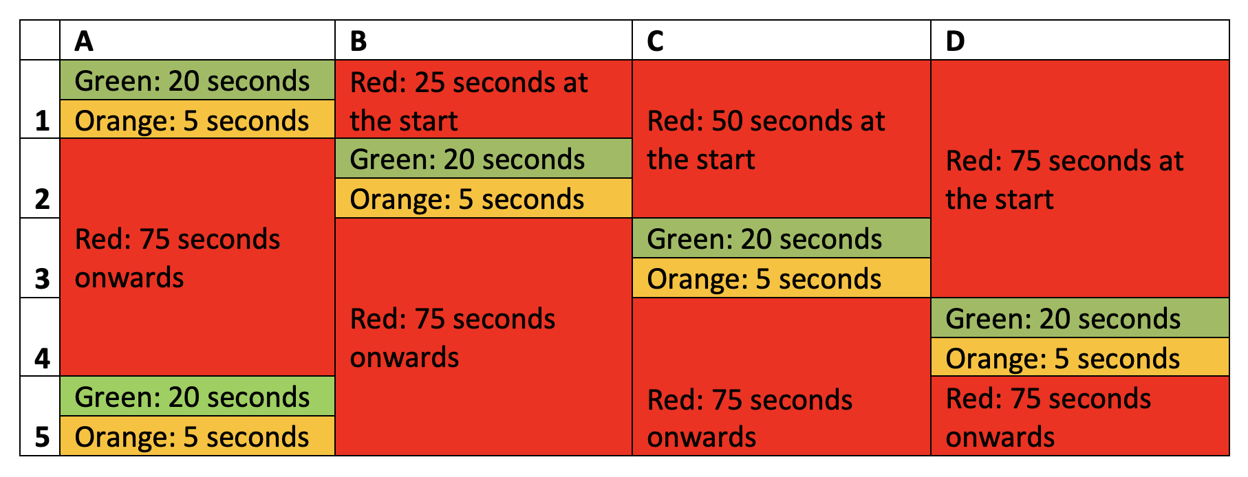
Initially, the signal for intersection B remains red for 25 seconds, for C it stays red for 50 seconds, and for D it remains red for 75 seconds. After completing the first cycle of signals for each direction, the signal follows a consistent pattern: green for 20 seconds, orange for 5 seconds, and red for 75 seconds for each way.
With the assumption that the signal remains green for 20 seconds and orange for 5 seconds for each intersection, let’s design the full traffic light system.
Circuit connections
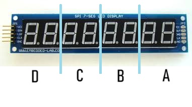
In this project, we’re using the MAX7219 IC-based 7-segment driver module to display the timer for each signal. The MAX7219 is an 8-digit common-cathode LED display driver that enables interfacing a microcontroller with 7-segment display units of up to 8 digits.
The four ways of the crossroad are mapped to the 7-segment displays on the module, as shown in the image below.
 In the module, the data pins of the 7-segment displays are connected to the SEG A to SEG G and DP pins of the MAX7219. The common-cathode terminals of the segments are linked to MAX7219’s DIG0 to DIG7 pins. The IC’s pins 4 and 9 are connected to the ground pin, while pin 19 is connected to the 5V terminal.
MAX7219’s pin 18 is also connected to 5V DC via an appropriate resistor. The DIN, LOAD, and CLK pins of the IC can be connected to Arduino’s digital I/O pins.
The MAX7219 communicates with the Arduino using an SPI-compatible interface. Specifically, the DIN, LOAD, and CLK pins of the IC are connected to Arduino’s pins 12, 10, and 11, respectively. The MAX7219 module is powered with 5V DC and grounded through the Arduino itself.
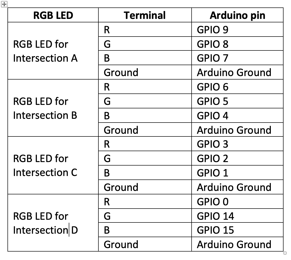
The red, green, and orange signals are represented using RGB LEDs. The circuit connections for the RGB LEDs are outlined in the table below.
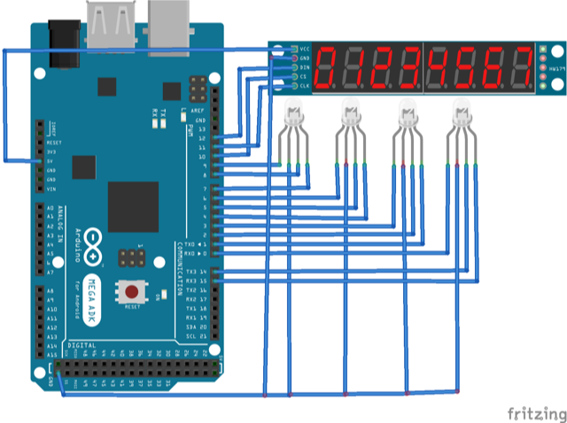
The circuit diagram for the project is shown in the image below.
The Arduino sketch
Before making the circuit connections, upload the following sketch to Arduino MEGA.
Next, the signal turns green for intersection B while remaining red for all other directions. At this stage, the timers are initialized using the following equations:
timb = b + w;timc = timb;timd = timb + c + w;tima = timd + d + w;
The timer for intersection B starts counting down while the signal stays green for a duration of b seconds and orange for w seconds. After the initialization and signal change, all the timers begin their countdown.
Eventually, the timers for intersections B and C reach zero and reset, while the timers for D and A continue counting down.
Subsequently, the signal switches to green for intersection C while all other paths remain red. The timers are initialized at this moment using the following equations:
timc = c + w;timd = timc;tima = timc + d + w;timb = tima + a + w;
The timer for intersection C operates during the green signal for c seconds and orange for w seconds. After initialization and signal transition, all the timers begin their countdown. Eventually, the timers for intersections C and D count down to zero and reset, while the timers for A and B continue their countdown.
Next, the signal turns green for intersection D while remaining red for all other directions. At this stage, the timers are initialized using the following equations:
timd = d + w;tima = timd;timb = timd + a + w;timc = timb + b + w;
The timer for intersection D starts running while the signal stays green for a duration of d seconds and orange for w seconds. After initialization and signal transition, all the timers begin their countdown.
Eventually, the timers for intersections D and A reach zero and reset, while the timers for B and C continue counting down.
This pattern repeats cyclically, ensuring a systematic and orderly traffic flow at the intersection.
The code
The Arduino sketch starts by importing the SPI library, which is essential for communication with the MAX7219 IC. Global variables are then defined to assign the pin numbers connected to MAX7219’s DIN, CLK, and LOAD pins.
An array-type variable is initialized to store 16-bit commands for the IC. Variables are declared to hold the durations of green signals for intersections A, B, C, and D, along with the timer values for each. A count variable is introduced to manage the countdown for each second, followed by variables for the timer digits. Additional variables are defined for the RGB LEDs’ pin assignments.
A character table is stored in the flash memory of the Arduino UNO using the PROGMEM construct. This table contains the byte data required to illuminate the LED segments for displaying digits “0” to “9.”
The functions:
An spiTransfer() function is defined for the shiftOut() function to transfer 16-bit data to MAX7219 IC. Each 16-bit data contains two bytes: the first byte specifies the MAX7219’s address of the register, and second byte provides the data to be written to the selected register. Both bytes are passed as arguments to this user-defined function. Both bytes are passed as arguments to this user-defined function, enabling precise communication with the display module.
The clearDisplay() function is defined, in which the spiTransfer() function is used to write “0x00” to all the digit registers clearing all the digits.
A function shutdown() is defined using the spiTransfer() function to write data to MAX7219’s shutdown mode register.
The init_7seg() function is defined to initialize the display. In this function, the MOSI, SCLK and CS pins are set to digital outputs. The CS pin is set to HIGH to select the MAX7219 on the SPI bus.
A value of “0x00” is transferred to the display test register (with a register address of “15” or “0x0F”) using the spiTransfer() function to set the MAX7219 to normal mode.
A value of “0x07” is transferred to scan the limit register (with a register address of “11” or “0x0B”), allowing it to use all eight digits.
A value of “0x00” is transferred to decode mode register (with a register address of “9” or “0x09”), which selects “no decode” for all of the digits.
A setChar() function is defined, which writes a value to MAX7219’s digit register. Both the value and digit are set as parameters of the function. This function provides a data validation for the digit number and passes the value. Then, the verified value is passed to a given digit register using the spiTransfer() function.
The function setA(), setB(), setC() and setD() are defined to set the colors of RGB LEDs for intersections A, B, C and D respectively.
In the setup() function, the init_7seg() and shutdown(false) functions are called. The spiTransfer(10, 8) function is called to set the intensity of the display. The display is cleared by calling the clearDisplay() function.
Arduino’s pins are then interfaced with the RGB LEDs, which are set as digital outputs using the pinMode() function.
The updateTimer() function is defined to countdown for all of the timers — from the initialized values at the signal change for each second. In the loop() function, the color for RGB LEDS are set according to signal matrix table and the timers are initialized for each signal change, followed by timer countdown for each second.
You may also like:


Filed Under: Arduino Projects, Electronic Projects, Video
Questions related to this article?
👉Ask and discuss on EDAboard.com and Electro-Tech-Online.com forums.
Tell Us What You Think!!
You must be logged in to post a comment.