Note: it’s recommended to follow this VHDL tutorial series in order, starting with the first tutorial. Follow the full series here.
In the previous Verilog Tutorial – 13, we learned how to design a 3×8 decoder and an 8×3 encoder in VHDL.
In this tutorial, we’ll:
- Write a Verilog program to build circuits for a 1×8 demultiplexer and an 8×1 multiplexer
- Verify the output waveform of program (digital circuit) with truth table of these multiplexer and demultiplexer circuits
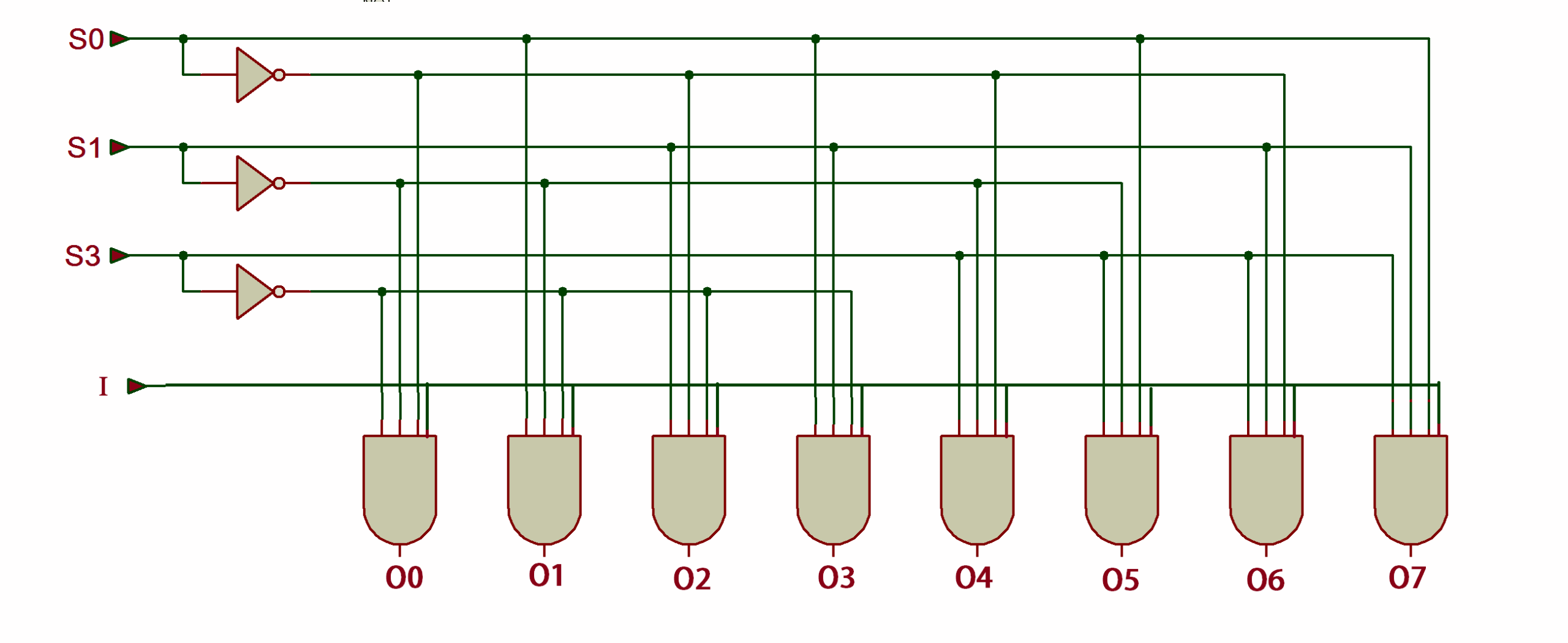
The 1×8 Demultiplexer circuit
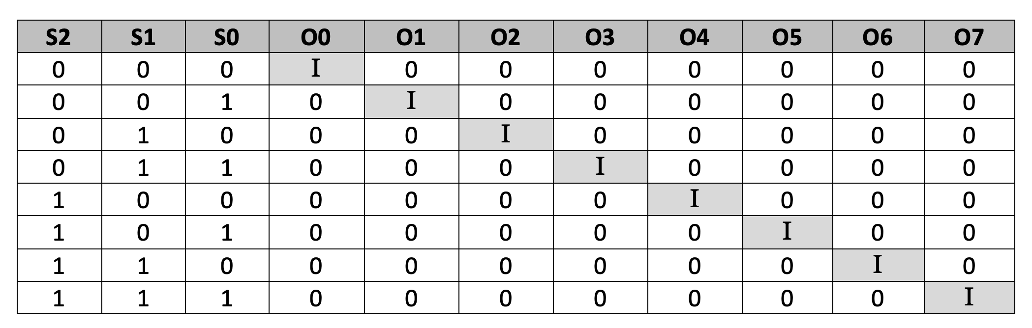
Truth table
Next, let’s write the Verilog program, compile and simulate it, and get the output in a waveform. We’ll also verify the output waveforms with the given truth table.
First, it’s important to review the step-by-step procedure provided in VHDL Tutorial – 3. In that tutorial, we learn how to design a project, edit and compile a program, create a waveform file, simulate the program, and generate the final output waveforms.
Verilog program
Gate-level modeling:
module demux18(o1,o2,o3,o4,o5,o6,o7,o8,D,s0,s1,s2);
input i,s0,s1,s2;
output o1,o2,o3,o4,o5,o6,o7,o8;
wire not_s0,not_s1,not_s2;
not(not_s0,s0);
not(not_s1,s1);
not(not_s2,s2);
and(o1,not_s0,not_s1,not_s2,i);
and(o2,s0,not_s1,not_s2,i);
and(o3,not_s0,s1,not_s2,i);
and(o4,s0,s1,not_s2,i);
and(o5,not_s0,not_s1,s2,i);
and(o6,s0,not_s1,s2,i);
and(o7,not_s0,s1,s2,i);
and(o8,s0,s1,s2,i);
endmodule
Dataflow modeling:
module demux18(o1,o2,o3,o4,o5,o6,o7,o8,D,s0,s1,s2);
input i,s0,s1,s2;
output o1,o2,o3,o4,o5,o6,o7,o8;
assign o1 = ~s0 & ~s1 & ~s2 & i;
assign o2 = s0 & ~s1 & ~s2 & i;
assign o3 = ~s0 & s1 & ~s2 & i;
assign o4 = s0 & s1 & ~s2 & i;
assign o5 = ~s0 & ~s1 & s2 & i;
assign o6= s0 & ~s1 & s2 & i;
assign o7 = ~s0 & s1 & s2 & i;
assign o8 = s0 & s1 & s2 & i;
endmodule
Now, compile the above program, creating a waveform file with all of the necessary inputs and outputs that are listed, and simulate the project.
Here are the results…
Waveform simulation
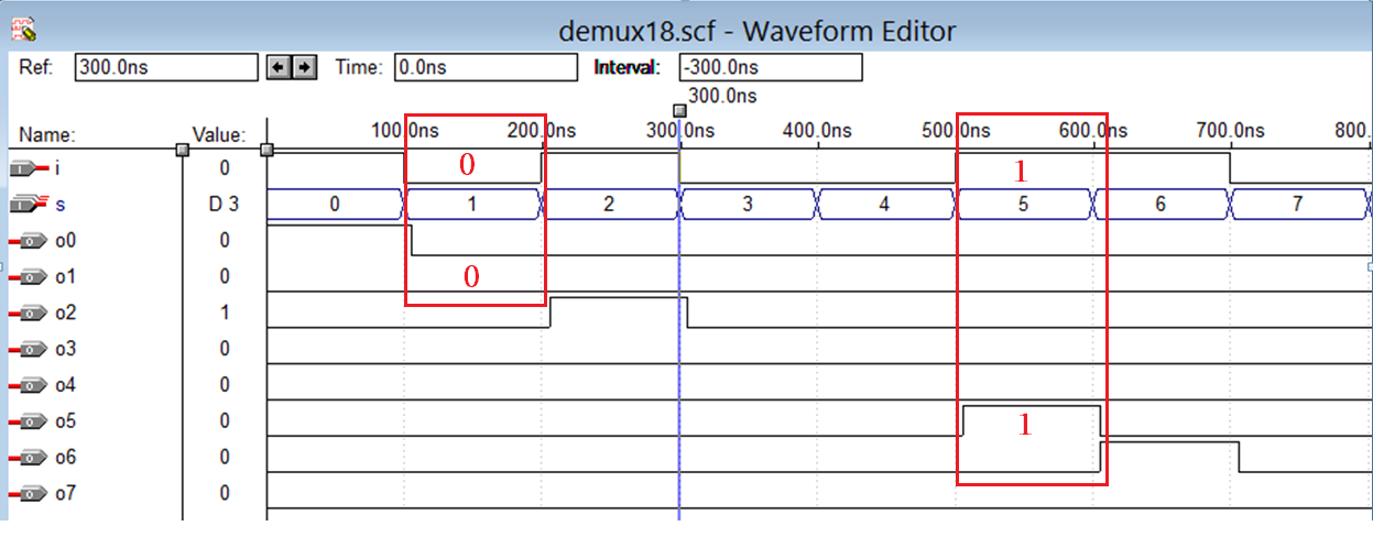
As shown above, the 8×1 multiplexer can be understood by examining the select lines and corresponding outputs. When the select lines (S2, S1, S0) are set to ‘001,’ input I₀ is routed to the output, resulting in ‘O₁ = 0.’
Similarly, when the select lines are ‘101,’ input I₅ is selected, and the output becomes ‘O₅ = 1.’ You can also verify other combinations of the select lines by observing how each input is connected to its corresponding output.
Next, let’s build the 8×1 multiplexer circuit.
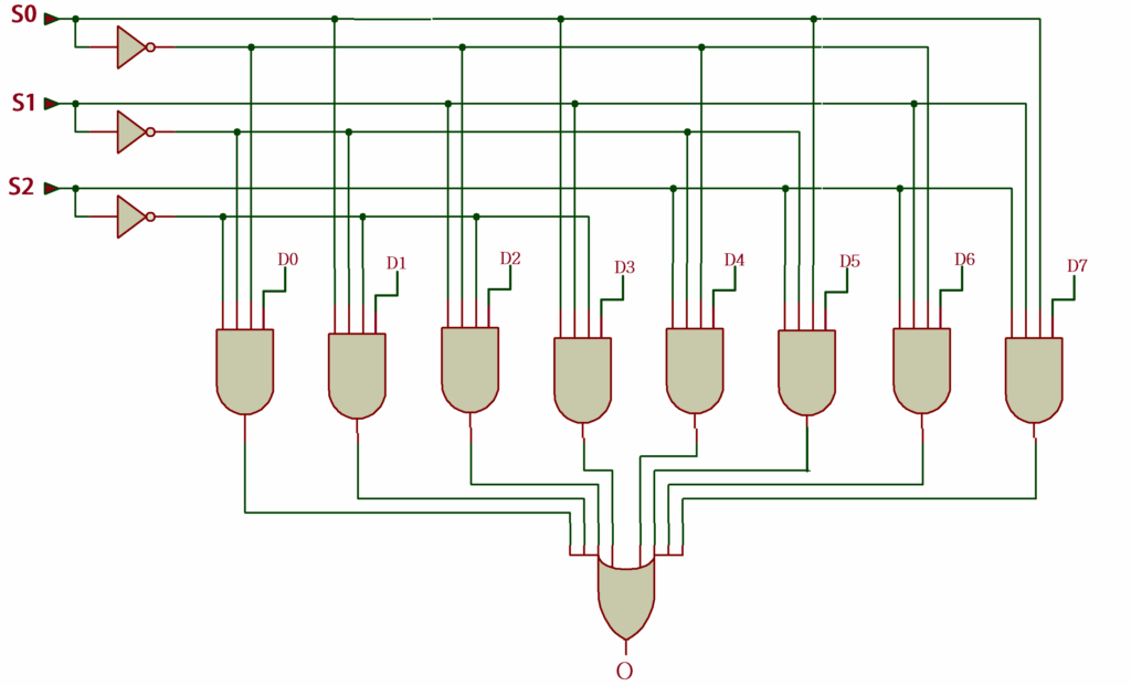
The 8×1 multiplexer circuit
 Verilog program:
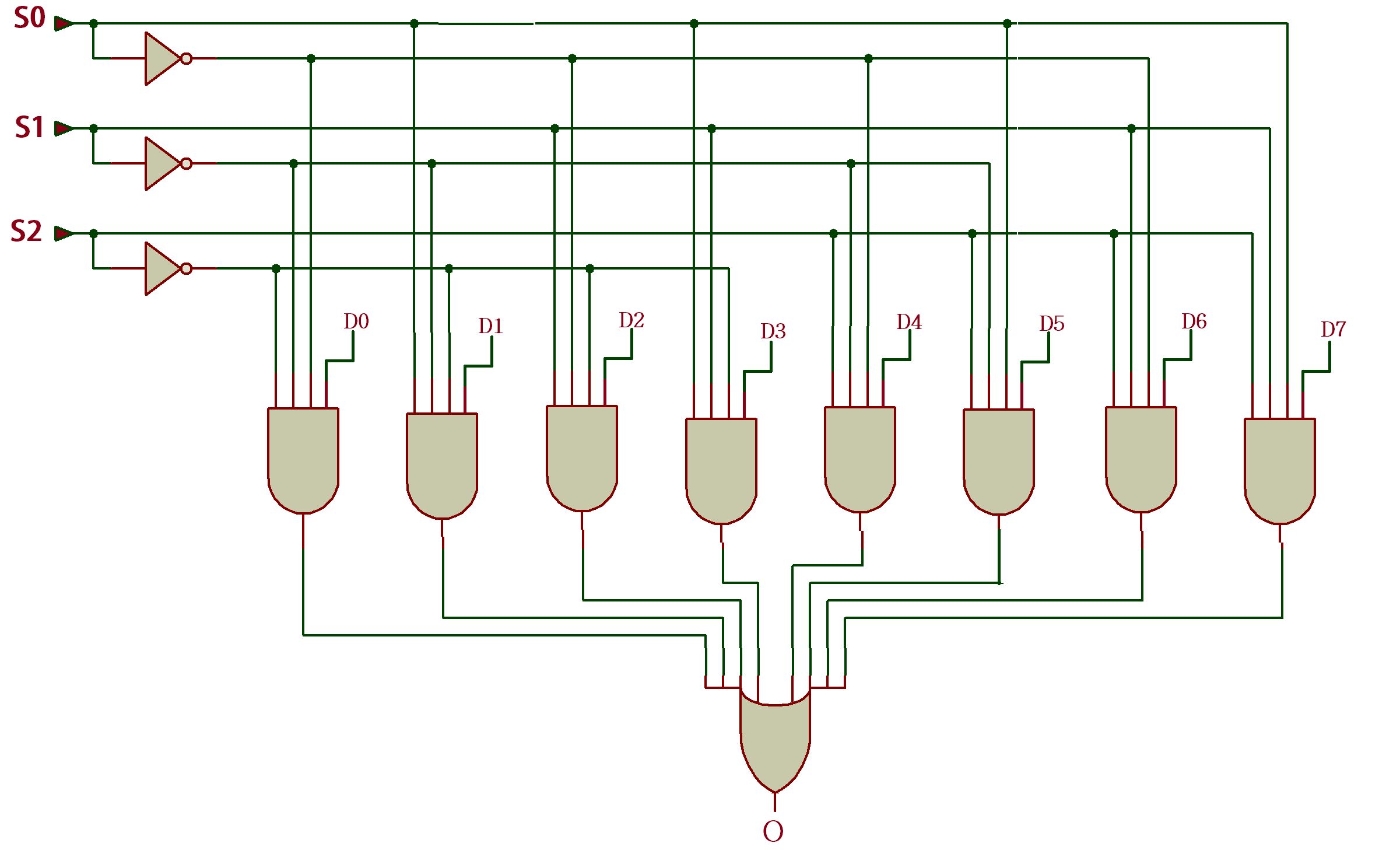
Gate-level modeling:
module mux81(o, D0, D1, D2, D3, D4, D5, D6, D7, S0, S1, S2);
input D0, D1, D2, D3, D4, D5, D6, D7, S0, S1, S2;
output o;
wire o1,o2,o3,o4,o5,o6,o7,o8,x,y,z;
not(x,S0);
not(y,S1);
not(z,S2);
and(o1,x,y,z,D0);
and(o2,S0,y,z,D1);
and(o3,x,S1,z,D2);
and(o4,S0,S1,z,D3);
and(o5,x,y,S2,D4);
and(o6,S0,y,S2,D5);
and(o7,x,S1,S2,D6);
and(o8,S0,S1,S2,D7);
or(o,o1,o2,o3,o4,o5,o6,o7,o8);
endmodule
Dataflow modeling:
module mux81(o, D0, D1, D2, D3, D4, D5, D6, D7, S0, S1, S2);
input D0, D1, D2, D3, D4, D5, D6, D7, S0, S1, S2;
output o;
wire o1,o2,o3,o4,o5,o6,o7,o8;
assign o1 = ~S0 & ~S1 & ~S2 & D0;
assign o2 = S0 & ~S1 & ~S2 & D1;
assign o3 = ~S0 & S1 & ~S2 & D2;
assign o4 = S0 & S1 & ~S2 & D3;
assign o5 = ~S0 & ~S1 & S2 & D4;
assign o6 = S0 & ~S1 & S2 & D5;
assign o7 = ~S0 & S1 & S2 & D6;
assign o8 = S0 & S1 & S2 & D7;
assign o = o1 | o2 | o3 | o4 | o5 | o6 | o7 | o8;
endmodule
Simulation waveform
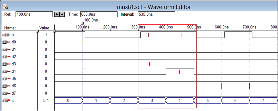
As shown in the figure, when the select lines (S2, S1, S0) are set to “011” and “100,” the corresponding inputs d₃ = 1 and d₄ = 1 are passed to the output, resulting in o = 1. You can verify additional select line combinations using the truth table.
In the next tutorial, we’ll design the RS flip-flop and the clocked RS latch.
You may also like:

Filed Under: Tutorials, Uncategorized
Questions related to this article?
👉Ask and discuss on Electro-Tech-Online.com and EDAboard.com forums.
Tell Us What You Think!!
You must be logged in to post a comment.